Brother International HL-3400CN Service Manual - Page 247
Cleaning, roller, sensor, Remove, screw, ST3x6, holding, cleaning, sensor., Disconnect, harness,
 |
UPC - 012502526223
View all Brother International HL-3400CN manuals
Add to My Manuals
Save this manual to your list of manuals |
Page 247 highlights
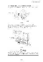
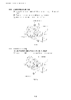
CHAPTER 7 DISASSEMBL Y & RE-ASSEMBLY 4.4.3 Cleaning roller sensor (PS5) (1) Remove the set screw ST3x6 (1 pc.) of the sensor base holding the cleaning roller sensor. (2) Disconnect the harness connected to the cleaning roller sensor. (3) Remove the cleaning roller sensor from the sensor base. \Cleaning roller sensor Sensor base @ Paper exit guide o) 0 0 .- . a 0 a Fig. 7-62 4.4.4 Paper full sensor (PS6) (1) Disconnect the harness connected to the paper full sensor. (2) Release the catch to remove the sensor unit from the paper exit guide. Paper exit guide ; , 0 0 0 a Paper full sensor Fig. 7-63 7-42
-
 1
1 -
2
-
3
-
4
-
5
-
6
-
7
-
8
-
9
-
10
-
11
-
12
-
13
-
14
-
15
-
16
-
17
-
18
-
19
-
20
-
21
-
22
-
23
-
24
-
25
-
26
-
27
-
28
-
29
-
30
-
31
-
32
-
33
-
34
-
35
-
36
-
37
-
38
-
39
-
40
-
41
-
42
-
43
-
44
-
45
-
46
-
47
-
48
-
49
-
50
-
51
-
52
-
53
-
54
-
55
-
56
-
57
-
58
-
59
-
60
-
61
-
62
-
63
-
64
-
65
-
66
-
67
-
68
-
69
-
70
-
71
-
72
-
73
-
74
-
75
-
76
-
77
-
78
-
79
-
80
-
81
-
82
-
83
-
84
-
85
-
86
-
87
-
88
-
89
-
90
-
91
-
92
-
93
-
94
-
95
-
96
-
97
-
98
-
99
-
100
-
101
-
102
-
103
-
104
-
105
-
106
-
107
-
108
-
109
-
110
-
111
-
112
-
113
-
114
-
115
-
116
-
117
-
118
-
119
-
120
-
121
-
122
-
123
-
124
-
125
-
126
-
127
-
128
-
129
-
130
-
131
-
132
-
133
-
134
-
135
-
136
-
137
-
138
-
139
-
140
-
141
-
142
-
143
-
144
-
145
-
146
-
147
-
148
-
149
-
150
-
151
-
152
-
153
-
154
-
155
-
156
-
157
-
158
-
159
-
160
-
161
-
162
-
163
-
164
-
165
-
166
-
167
-
168
-
169
-
170
-
171
-
172
-
173
-
174
-
175
-
176
-
177
-
178
-
179
-
180
-
181
-
182
-
183
-
184
-
185
-
186
-
187
-
188
-
189
-
190
-
191
-
192
-
193
-
194
-
195
-
196
-
197
-
198
-
199
-
200
-
201
-
202
-
203
-
204
-
205
-
206
-
207
-
208
-
209
-
210
-
211
-
212
-
213
-
214
-
215
-
216
-
217
-
218
-
219
-
220
-
221
-
222
-
223
-
224
-
225
-
226
-
227
-
228
-
229
-
230
-
231
-
232
-
233
-
234
-
235
-
236
-
237
-
238
-
239
-
240
-
241
-
 242
242 -
 243
243 -
 244
244 -
 245
245 -
 246
246 -
 247
247 -
 248
248 -
 249
249 -
 250
250 -
 251
251 -
 252
252 -
253
-
254
-
255
-
256
-
257
-
258
-
259
-
260
-
261
-
262
-
263
-
264
-
265
-
266
-
267
-
268
-
269
-
270
-
271
-
272
-
273
-
274
-
275
-
276
-
277
-
278
-
279
-
280
-
281
-
282
-
283
-
284
-
285
-
286
-
287
-
288
-
289
-
290
-
291
-
292
-
293
-
294
-
295
-
296
-
297
-
298
-
299
-
300
-
301
-
302
-
303
-
304
-
305
-
306
-
307
-
308
-
309
-
310
-
311
-
312
-
313
-
314
-
315
-
316
-
317
-
318
-
319
-
320
-
321
-
322
-
323
-
324
-
325
-
326
-
327
-
328
-
329
-
330
-
331
-
332
-
333
-
334
-
335
-
336
-
337
-
338
-
339
-
340
-
341
-
342
-
343
-
344
-
345
-
346
-
347
 |
 |

CHAPTER
7
DISASSEMBL
Y
&
RE
-ASSEMBLY
4.4.3
Cleaning
roller
sensor
(PS5)
(1)
Remove
the
set
screw
ST3x6
(1
pc.)
of
the
sensor
base
holding
the
cleaning
roller
sensor.
(2)
Disconnect
the
harness
connected
to
the
cleaning
roller
sensor.
(3)
Remove
the
cleaning
roller
sensor
from
the
sensor
base.
Cleaning
roller
sensor
\
Sensor
base
@
o)
Paper
exit
guide
Fig.
7-62
.-
0
.
a
0
0
a
4.4.4
Paper
full
sensor
(PS6)
(1)
Disconnect
the
harness
connected
to
the
paper
full
sensor.
(2)
Release
the
catch
to
remove
the
sensor
unit
from
the
paper
exit
guide.
;
Paper
full
sensor
Fig.
7-63
Paper
exit
guide
,
0
0
0
a
7-42