Brother International HL-3400CN Service Manual - Page 245
DISASSEMBLY, ASSEMBLY, cover, Paper, assembly
 |
UPC - 012502526223
View all Brother International HL-3400CN manuals
Add to My Manuals
Save this manual to your list of manuals |
Page 245 highlights
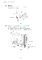
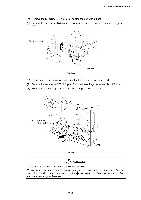
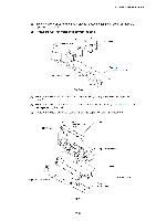
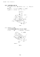
CHAPTER 7 DISASSEMBLY & RE-ASSEMBLY 4.4 4.4.1 Paper Exit Unit Rear cover 3 (U) (1) Remove the rear cover 3 (R). (Refer to subsection 4.3.6 in this chapter.) (2) Release the two hooks to remove the rear cover 3 (U). (3) Remove the rear cover (U) caps (2 pcs.) from the rear cover 3 (U) if necessary. Rear cover 3 (U) Rear cover (U) cap 3 Fig. 7-58 4.4.2 Top cover ( 'aper exit unit :1I Fuser fan (FUFAN) ( ,00ling fan EX) (1) Disconnect the connector in the cover assembly. (2) Remove the support pins SP4x3 (2 pcs.) at the left and right sides that act as the paper exit unit hinges. (3) Remove the paper exit unit from the printer. (4) Remove the side cover assembly from the paper exit unit 3. Paper exit unit 3 Side cover assembly Fig. 7-59 7-40
-
 1
1 -
2
-
3
-
4
-
5
-
6
-
7
-
8
-
9
-
10
-
11
-
12
-
13
-
14
-
15
-
16
-
17
-
18
-
19
-
20
-
21
-
22
-
23
-
24
-
25
-
26
-
27
-
28
-
29
-
30
-
31
-
32
-
33
-
34
-
35
-
36
-
37
-
38
-
39
-
40
-
41
-
42
-
43
-
44
-
45
-
46
-
47
-
48
-
49
-
50
-
51
-
52
-
53
-
54
-
55
-
56
-
57
-
58
-
59
-
60
-
61
-
62
-
63
-
64
-
65
-
66
-
67
-
68
-
69
-
70
-
71
-
72
-
73
-
74
-
75
-
76
-
77
-
78
-
79
-
80
-
81
-
82
-
83
-
84
-
85
-
86
-
87
-
88
-
89
-
90
-
91
-
92
-
93
-
94
-
95
-
96
-
97
-
98
-
99
-
100
-
101
-
102
-
103
-
104
-
105
-
106
-
107
-
108
-
109
-
110
-
111
-
112
-
113
-
114
-
115
-
116
-
117
-
118
-
119
-
120
-
121
-
122
-
123
-
124
-
125
-
126
-
127
-
128
-
129
-
130
-
131
-
132
-
133
-
134
-
135
-
136
-
137
-
138
-
139
-
140
-
141
-
142
-
143
-
144
-
145
-
146
-
147
-
148
-
149
-
150
-
151
-
152
-
153
-
154
-
155
-
156
-
157
-
158
-
159
-
160
-
161
-
162
-
163
-
164
-
165
-
166
-
167
-
168
-
169
-
170
-
171
-
172
-
173
-
174
-
175
-
176
-
177
-
178
-
179
-
180
-
181
-
182
-
183
-
184
-
185
-
186
-
187
-
188
-
189
-
190
-
191
-
192
-
193
-
194
-
195
-
196
-
197
-
198
-
199
-
200
-
201
-
202
-
203
-
204
-
205
-
206
-
207
-
208
-
209
-
210
-
211
-
212
-
213
-
214
-
215
-
216
-
217
-
218
-
219
-
220
-
221
-
222
-
223
-
224
-
225
-
226
-
227
-
228
-
229
-
230
-
231
-
232
-
233
-
234
-
235
-
236
-
237
-
238
-
239
-
 240
240 -
 241
241 -
 242
242 -
 243
243 -
 244
244 -
 245
245 -
 246
246 -
 247
247 -
 248
248 -
 249
249 -
 250
250 -
251
-
252
-
253
-
254
-
255
-
256
-
257
-
258
-
259
-
260
-
261
-
262
-
263
-
264
-
265
-
266
-
267
-
268
-
269
-
270
-
271
-
272
-
273
-
274
-
275
-
276
-
277
-
278
-
279
-
280
-
281
-
282
-
283
-
284
-
285
-
286
-
287
-
288
-
289
-
290
-
291
-
292
-
293
-
294
-
295
-
296
-
297
-
298
-
299
-
300
-
301
-
302
-
303
-
304
-
305
-
306
-
307
-
308
-
309
-
310
-
311
-
312
-
313
-
314
-
315
-
316
-
317
-
318
-
319
-
320
-
321
-
322
-
323
-
324
-
325
-
326
-
327
-
328
-
329
-
330
-
331
-
332
-
333
-
334
-
335
-
336
-
337
-
338
-
339
-
340
-
341
-
342
-
343
-
344
-
345
-
346
-
347
 |
 |

CHAPTER
7
DISASSEMBLY
&
RE
-ASSEMBLY
4.4
Paper
Exit
Unit
4.4.1
Rear
cover
3
(U)
(1)
Remove
the
rear
cover
3
(R).
(Refer
to
subsection
4.3.6
in
this
chapter.)
(2)
Release
the
two
hooks
to
remove
the
rear
cover
3
(U).
(3)
Remove
the
rear
cover
(U)
caps
(2
pcs.)
from
the
rear
cover
3
(U)
if
necessary.
Rear
cover
3
(U)
Rear
cover
(U)
cap
Fig.
7-58
3
4.4.2
Top
cover
(
'aper
exit
unit
:1
I
Fuser
fan
(FUFAN)
(
,00ling
fan
EX)
(1)
Disconnect
the
connector
in
the
cover
assembly.
(2)
Remove
the
support
pins
SP4x3
(2
pcs.)
at
the
left
and
right
sides
that
act
as
the
paper
exit
unit
hinges.
(3)
Remove
the
paper
exit
unit
from
the
printer.
(4)
Remove
the
side
cover
assembly
from
the
paper
exit
unit
3.
Paper
exit
unit
3
Side
cover
assembly
Fig.
7-59
7-40