Brother International HL-3400CN Service Manual - Page 250
ST4x6
 |
UPC - 012502526223
View all Brother International HL-3400CN manuals
Add to My Manuals
Save this manual to your list of manuals |
Page 250 highlights
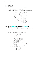
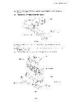
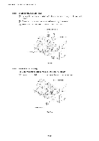
HL-3400CN SERVICE MANUAL 4.5 4.5.1 Front of the Printer Front outer cover ( (1) Open the front cover unit 3. (2) Remove the set screws BT4x10 (2 pcs.) from the front cover unit 3. (3) Unhook the five hooks and remove the front outer cover. r7- Hook Tz /1J Front outer cover Fig. 7-67 4.5.2 Front cover unit 3 (1) Close the front cover. (2) Remove the set screw ST4x6 (6 pcs.) to remove the front cover supports at left and right sides from the frame. (3) Remove the set screw ST3x6 (1 pc.) from the front hinge (L) to remove the front hinge support from the frame. Front hinge support 0 0 0 Fig. 7-68 7-45 Front cover
-
 1
1 -
2
-
3
-
4
-
5
-
6
-
7
-
8
-
9
-
10
-
11
-
12
-
13
-
14
-
15
-
16
-
17
-
18
-
19
-
20
-
21
-
22
-
23
-
24
-
25
-
26
-
27
-
28
-
29
-
30
-
31
-
32
-
33
-
34
-
35
-
36
-
37
-
38
-
39
-
40
-
41
-
42
-
43
-
44
-
45
-
46
-
47
-
48
-
49
-
50
-
51
-
52
-
53
-
54
-
55
-
56
-
57
-
58
-
59
-
60
-
61
-
62
-
63
-
64
-
65
-
66
-
67
-
68
-
69
-
70
-
71
-
72
-
73
-
74
-
75
-
76
-
77
-
78
-
79
-
80
-
81
-
82
-
83
-
84
-
85
-
86
-
87
-
88
-
89
-
90
-
91
-
92
-
93
-
94
-
95
-
96
-
97
-
98
-
99
-
100
-
101
-
102
-
103
-
104
-
105
-
106
-
107
-
108
-
109
-
110
-
111
-
112
-
113
-
114
-
115
-
116
-
117
-
118
-
119
-
120
-
121
-
122
-
123
-
124
-
125
-
126
-
127
-
128
-
129
-
130
-
131
-
132
-
133
-
134
-
135
-
136
-
137
-
138
-
139
-
140
-
141
-
142
-
143
-
144
-
145
-
146
-
147
-
148
-
149
-
150
-
151
-
152
-
153
-
154
-
155
-
156
-
157
-
158
-
159
-
160
-
161
-
162
-
163
-
164
-
165
-
166
-
167
-
168
-
169
-
170
-
171
-
172
-
173
-
174
-
175
-
176
-
177
-
178
-
179
-
180
-
181
-
182
-
183
-
184
-
185
-
186
-
187
-
188
-
189
-
190
-
191
-
192
-
193
-
194
-
195
-
196
-
197
-
198
-
199
-
200
-
201
-
202
-
203
-
204
-
205
-
206
-
207
-
208
-
209
-
210
-
211
-
212
-
213
-
214
-
215
-
216
-
217
-
218
-
219
-
220
-
221
-
222
-
223
-
224
-
225
-
226
-
227
-
228
-
229
-
230
-
231
-
232
-
233
-
234
-
235
-
236
-
237
-
238
-
239
-
240
-
241
-
242
-
243
-
244
-
 245
245 -
 246
246 -
 247
247 -
 248
248 -
 249
249 -
 250
250 -
 251
251 -
 252
252 -
 253
253 -
 254
254 -
 255
255 -
256
-
257
-
258
-
259
-
260
-
261
-
262
-
263
-
264
-
265
-
266
-
267
-
268
-
269
-
270
-
271
-
272
-
273
-
274
-
275
-
276
-
277
-
278
-
279
-
280
-
281
-
282
-
283
-
284
-
285
-
286
-
287
-
288
-
289
-
290
-
291
-
292
-
293
-
294
-
295
-
296
-
297
-
298
-
299
-
300
-
301
-
302
-
303
-
304
-
305
-
306
-
307
-
308
-
309
-
310
-
311
-
312
-
313
-
314
-
315
-
316
-
317
-
318
-
319
-
320
-
321
-
322
-
323
-
324
-
325
-
326
-
327
-
328
-
329
-
330
-
331
-
332
-
333
-
334
-
335
-
336
-
337
-
338
-
339
-
340
-
341
-
342
-
343
-
344
-
345
-
346
-
347
 |
 |

HL-3400CN
SERVICE
MANUAL
4.5
Front
of
the
Printer
4.5.1
Front
outer
cover
(
(1)
Open
the
front
cover
unit
3.
(2)
Remove
the
set
screws
BT4x10
(2
pcs.)
from
the
front
cover
unit
3.
(3)
Unhook
the
five
hooks
and
remove
the
front
outer
cover.
7
-
r
Hook
Front
outer
cover
/1J
Fig.
7-67
Tz
4.5.2
Front
cover
unit
3
(1)
Close
the
front
cover.
(2)
Remove
the
set
screw
ST4x6
(6
pcs.)
to
remove
the
front
cover
supports
at
left
and
right
sides
from
the
frame.
(3)
Remove
the
set
screw
ST3x6
(1
pc.)
from
the
front
hinge
(L)
to
remove
the
front
hinge
support
from
the
frame.
Front
hinge
support
0
0
0
Fig.
7-68
Front
cover
7-45