Brother International HL-3400CN Service Manual - Page 51
board
 |
UPC - 012502526223
View all Brother International HL-3400CN manuals
Add to My Manuals
Save this manual to your list of manuals |
Page 51 highlights
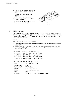
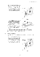
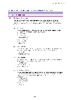
CHAPTER 3iNSTALLATION (4) Insert the four pins supplied with the HDD unit into the bottom of the HDD. Pin C.---------- C (5) Connect the flat cable to the HDD with the keyed side downwards, ensuring it is correctly aligned. Fig. 3-35 (6) Assemble the four HDD pins into the four holes of the main controller board and secure the pillars with the screws provided from the rear of the PCB. (7) Connect the flat cable to the main controller board. (8) Install the main controller board into the printer by sliding it into the guide rails. (9) Secure the main controller board with the two screws. 3-22 Flat cable Fig. 3-36 HDD ) 0 I a 6 6 Fig. 3-37 Flat cable 0 Fig. 3-38
-
 1
1 -
2
-
3
-
4
-
5
-
6
-
7
-
8
-
9
-
10
-
11
-
12
-
13
-
14
-
15
-
16
-
17
-
18
-
19
-
20
-
21
-
22
-
23
-
24
-
25
-
26
-
27
-
28
-
29
-
30
-
31
-
32
-
33
-
34
-
35
-
36
-
37
-
38
-
39
-
40
-
41
-
42
-
43
-
44
-
45
-
 46
46 -
 47
47 -
 48
48 -
 49
49 -
 50
50 -
 51
51 -
 52
52 -
 53
53 -
 54
54 -
 55
55 -
 56
56 -
57
-
58
-
59
-
60
-
61
-
62
-
63
-
64
-
65
-
66
-
67
-
68
-
69
-
70
-
71
-
72
-
73
-
74
-
75
-
76
-
77
-
78
-
79
-
80
-
81
-
82
-
83
-
84
-
85
-
86
-
87
-
88
-
89
-
90
-
91
-
92
-
93
-
94
-
95
-
96
-
97
-
98
-
99
-
100
-
101
-
102
-
103
-
104
-
105
-
106
-
107
-
108
-
109
-
110
-
111
-
112
-
113
-
114
-
115
-
116
-
117
-
118
-
119
-
120
-
121
-
122
-
123
-
124
-
125
-
126
-
127
-
128
-
129
-
130
-
131
-
132
-
133
-
134
-
135
-
136
-
137
-
138
-
139
-
140
-
141
-
142
-
143
-
144
-
145
-
146
-
147
-
148
-
149
-
150
-
151
-
152
-
153
-
154
-
155
-
156
-
157
-
158
-
159
-
160
-
161
-
162
-
163
-
164
-
165
-
166
-
167
-
168
-
169
-
170
-
171
-
172
-
173
-
174
-
175
-
176
-
177
-
178
-
179
-
180
-
181
-
182
-
183
-
184
-
185
-
186
-
187
-
188
-
189
-
190
-
191
-
192
-
193
-
194
-
195
-
196
-
197
-
198
-
199
-
200
-
201
-
202
-
203
-
204
-
205
-
206
-
207
-
208
-
209
-
210
-
211
-
212
-
213
-
214
-
215
-
216
-
217
-
218
-
219
-
220
-
221
-
222
-
223
-
224
-
225
-
226
-
227
-
228
-
229
-
230
-
231
-
232
-
233
-
234
-
235
-
236
-
237
-
238
-
239
-
240
-
241
-
242
-
243
-
244
-
245
-
246
-
247
-
248
-
249
-
250
-
251
-
252
-
253
-
254
-
255
-
256
-
257
-
258
-
259
-
260
-
261
-
262
-
263
-
264
-
265
-
266
-
267
-
268
-
269
-
270
-
271
-
272
-
273
-
274
-
275
-
276
-
277
-
278
-
279
-
280
-
281
-
282
-
283
-
284
-
285
-
286
-
287
-
288
-
289
-
290
-
291
-
292
-
293
-
294
-
295
-
296
-
297
-
298
-
299
-
300
-
301
-
302
-
303
-
304
-
305
-
306
-
307
-
308
-
309
-
310
-
311
-
312
-
313
-
314
-
315
-
316
-
317
-
318
-
319
-
320
-
321
-
322
-
323
-
324
-
325
-
326
-
327
-
328
-
329
-
330
-
331
-
332
-
333
-
334
-
335
-
336
-
337
-
338
-
339
-
340
-
341
-
342
-
343
-
344
-
345
-
346
-
347
 |
 |

CHAPTER
3
iNSTALLATION
(4)
Insert
the
four
pins
supplied
with
the
HDD
unit
into
the
bottom
of
the
HDD.
(5)
Connect
the
flat
cable
to
the
HDD
with
the
keyed
side
downwards,
ensuring
it
is
correctly
aligned.
(6)
Assemble
the
four
HDD
pins
into
the
four
holes
of
the
main
controller
board
and
secure
the
pillars
with
the
screws
provided
from
the
rear
of
the
PCB.
(7)
Connect
the
flat
cable
to
the
main
controller
board.
0
(8)
Install
the
main
controller
board
into
the
printer
by
sliding
it
into
the
guide
rails.
(9)
Secure
the
main
controller
board
with
the
two
screws.
0
C
Fig.
3-35
Flat
cable
Fig.
3-36
)
Pin
C
.----------
I
a
6
6
Fig.
3-37
Fig.
3-38
HDD
Flat
cable
3-22