Dell Broadcom NetXtreme Family of Adapters Broadcom NetXtreme 57XX User Guide - Page 102
Edit Target IP Address, IP Address
 |
View all Dell Broadcom NetXtreme Family of Adapters manuals
Add to My Manuals
Save this manual to your list of manuals |
Page 102 highlights
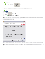
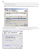
10. If you want to configure LiveLink, select Yes, otherwise select No, then click Next. 11. Select the probe interval (the number of seconds between each retransmission of a link packet to the probe target) and the maximum number of probe retries (the number of consecutively missed responses from a probe target before a failover is triggered). 12. Set the Probe VLAN ID to allow for connectivity with probe targets residing on a tagged VLAN. The number set must match the VLAN ID of the probe targets as well as the port(s) on the switch to which the team is connected. NOTE: Each LiveLink enabled team can only communicate with Probe Targets on a single VLAN. Also, VLAN ID 0 is equivalent to an untagged network. If the Probe VLAN ID is set to a value other than 0, then a VLAN must be created with an identical VLAN tag value (see Step 18.). 13. Click the probe target at the top of the list, click Edit Target IP Address, type the target IP address in the IP Address box for one or all probe targets, and then click OK. Click Next. NOTE: Only the first probe target is required. You can specify up to three additional probe targets to serve as backups by assigning IP addresses to the other probe targets.
-
 1
1 -
2
-
3
-
4
-
5
-
6
-
7
-
8
-
9
-
10
-
11
-
12
-
13
-
14
-
15
-
16
-
17
-
18
-
19
-
20
-
21
-
22
-
23
-
24
-
25
-
26
-
27
-
28
-
29
-
30
-
31
-
32
-
33
-
34
-
35
-
36
-
37
-
38
-
39
-
40
-
41
-
42
-
43
-
44
-
45
-
46
-
47
-
48
-
49
-
50
-
51
-
52
-
53
-
54
-
55
-
56
-
57
-
58
-
59
-
60
-
61
-
62
-
63
-
64
-
65
-
66
-
67
-
68
-
69
-
70
-
71
-
72
-
73
-
74
-
75
-
76
-
77
-
78
-
79
-
80
-
81
-
82
-
83
-
84
-
85
-
86
-
87
-
88
-
89
-
90
-
91
-
92
-
93
-
94
-
95
-
96
-
 97
97 -
 98
98 -
 99
99 -
 100
100 -
 101
101 -
 102
102 -
 103
103 -
 104
104 -
 105
105 -
 106
106 -
 107
107 -
108
-
109
-
110
-
111
-
112
-
113
-
114
-
115
-
116
-
117
-
118
-
119
-
120
-
121
-
122
-
123
-
124
-
125
-
126
-
127
-
128
-
129
-
130
-
131
-
132
-
133
-
134
-
135
-
136
-
137
-
138
-
139
-
140
-
141
-
142
-
143
-
144
-
145
-
146
-
147
-
148
-
149
-
150
-
151
-
152
-
153
-
154
-
155
-
156
-
157
-
158
-
159
-
160
-
161
-
162
-
163
-
164
-
165
-
166
-
167
-
168
-
169
-
170
-
171
-
172
-
173
-
174
-
175
-
176
-
177
-
178
 |
 |
