Dell Broadcom NetXtreme Family of Adapters Broadcom NetXtreme 57XX User Guide - Page 138
Teaming Concepts
 |
View all Dell Broadcom NetXtreme Family of Adapters manuals
Add to My Manuals
Save this manual to your list of manuals |
Page 138 highlights
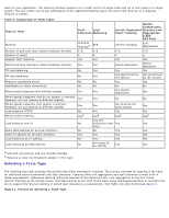
IP Internet Protocol LACP Link Aggregation Control Protocol Link Aggregation (802.3ad) Switch-dependent load balancing and failover type of team with LACP in which the intermediate driver manages outgoing traffic and the switch manages incoming traffic. LOM LAN on Motherboard MAC media access control NDIS Network Driver Interface Specification NLB Network Load Balancing (Microsoft) PXE Preboot Execution Environment RAID Redundant array of inexpensive disks Smart Load Balance and Failover Switch-independent failover type of team in which the primary team member handles all incoming and outgoing traffic while the standby team member is idle until a failover event (for example, loss of link occurs). The intermediate driver (BASP) manages incoming/outgoing traffic. Smart Load Balancing (SLB) Switch-independent load balancing and failover type of team, in which the intermediate driver manages outgoing/incoming traffic. TCP Transmission Control Protocol UDP User Datagram Protocol WINS Windows name service WLBS Windows Load Balancing Service Teaming Concepts Network Addressing Teaming and Network Addresses Description of Teaming Types The concept of grouping multiple physical devices to provide fault tolerance and load balancing is not new. It has been around for years. Storage devices use RAID technology to group individual hard drives. Switch ports can be grouped together using technologies such as Cisco Gigabit EtherChannel, IEEE 802.3ad Link Aggregation, Bay Network Multilink Trunking, and Extreme Network Load Sharing. Network interfaces on Dell servers can be grouped together into a team of physical ports called a virtual adapter. Network Addressing To understand how teaming works, it is important to understand how node communications work in an Ethernet network. This document is based on the assumption that the reader is familiar with the basics of IP and Ethernet network communications. The following information provides a high-level overview of the concepts of network addressing used in an Ethernet network. Every Ethernet network interface in a host platform, such as a computer system, requires a globally unique Layer 2 address and at least one globally unique Layer 3 address. Layer 2 is the Data Link Layer, and Layer 3 is the Network layer as defined in the OSI model. The Layer 2 address is assigned to the hardware and is often referred to as the MAC address or physical address. This address is pre-programmed at the factory and stored in NVRAM on a network interface card or on the system motherboard for an embedded LAN interface. The Layer 3 addresses are referred to as the protocol or logical address assigned to the software stack. IP and IPX are examples of Layer 3 protocols. In addition, Layer 4 (Transport Layer) uses port numbers for each network upper level protocol such as Telnet or FTP. These port numbers are used to differentiate traffic flows across applications. Layer 4 protocols such as TCP or UDP are most commonly used in today's networks. The combination of the IP address and the TCP port number is called a socket. Ethernet devices communicate with other Ethernet devices using the MAC address, not the IP address. However, most applications work with a host name that is translated to an IP address by a Naming Service such as WINS and DNS. Therefore, a method of identifying the MAC address assigned to the IP address is required. The Address Resolution Protocol for an IP network provides this mechanism. For IPX, the MAC address is part of the network address and ARP is not required. ARP is implemented using an ARP Request and ARP Reply frame. ARP Requests are typically sent to a broadcast address while the ARP Reply is typically sent as unicast traffic. A unicast address corresponds to a single MAC address or a single IP address. A broadcast address is sent to all devices on a network. Teaming and Network Addresses
-
 1
1 -
2
-
3
-
4
-
5
-
6
-
7
-
8
-
9
-
10
-
11
-
12
-
13
-
14
-
15
-
16
-
17
-
18
-
19
-
20
-
21
-
22
-
23
-
24
-
25
-
26
-
27
-
28
-
29
-
30
-
31
-
32
-
33
-
34
-
35
-
36
-
37
-
38
-
39
-
40
-
41
-
42
-
43
-
44
-
45
-
46
-
47
-
48
-
49
-
50
-
51
-
52
-
53
-
54
-
55
-
56
-
57
-
58
-
59
-
60
-
61
-
62
-
63
-
64
-
65
-
66
-
67
-
68
-
69
-
70
-
71
-
72
-
73
-
74
-
75
-
76
-
77
-
78
-
79
-
80
-
81
-
82
-
83
-
84
-
85
-
86
-
87
-
88
-
89
-
90
-
91
-
92
-
93
-
94
-
95
-
96
-
97
-
98
-
99
-
100
-
101
-
102
-
103
-
104
-
105
-
106
-
107
-
108
-
109
-
110
-
111
-
112
-
113
-
114
-
115
-
116
-
117
-
118
-
119
-
120
-
121
-
122
-
123
-
124
-
125
-
126
-
127
-
128
-
129
-
130
-
131
-
132
-
 133
133 -
 134
134 -
 135
135 -
 136
136 -
 137
137 -
 138
138 -
 139
139 -
 140
140 -
 141
141 -
 142
142 -
 143
143 -
144
-
145
-
146
-
147
-
148
-
149
-
150
-
151
-
152
-
153
-
154
-
155
-
156
-
157
-
158
-
159
-
160
-
161
-
162
-
163
-
164
-
165
-
166
-
167
-
168
-
169
-
170
-
171
-
172
-
173
-
174
-
175
-
176
-
177
-
178
 |
 |
