Dell PowerEdge R805 Hardware Owner's Manual (PDF)
Dell PowerEdge R805 Manual
 |
View all Dell PowerEdge R805 manuals
Add to My Manuals
Save this manual to your list of manuals |
Dell PowerEdge R805 manual content summary:
- Dell PowerEdge R805 | Hardware Owner's Manual (PDF) - Page 1
Dell™ PowerEdge™ R805 Systems Hardware Owner's Manual www.dell.com | support.dell.com - Dell PowerEdge R805 | Hardware Owner's Manual (PDF) - Page 2
to hardware or loss of data and tells you how to avoid the problem. CAUTION Dell, the DELL logo, PowerEdge, and Dell OpenManage are trademarks of Dell Inc.; AMD and AMD Opteron are registered trademarks and AMD PowerNow! is a trademark of Advanced Micro Devices; Microsoft, Windows, Windows Server - Dell PowerEdge R805 | Hardware Owner's Manual (PDF) - Page 3
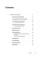
Startup 12 Front-Panel Features and Indicators 14 Hard-Drive Indicator Codes 17 Back-Panel Features and Indicators 18 Connecting External Devices 19 Power Indicator Codes 20 NIC Indicator Codes 21 LCD Status Messages 22 Solving Problems Described by LCD Status Messages 34 Removing LCD - Dell PowerEdge R805 | Hardware Owner's Manual (PDF) - Page 4
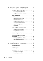
Program 48 System Setup Options 48 Main Screen 48 Memory Information Screen 51 CPU Information Screen 52 Integrated Devices Screen 54 Serial Password 62 Disabling a Forgotten Password 63 Baseboard Management Controller Configuration 63 Entering the BMC Setup Module 64 BMC Setup - Dell PowerEdge R805 | Hardware Owner's Manual (PDF) - Page 5
a Hard-Drive Carrier 76 Removing a Hard Drive From a Hard-Drive Carrier 76 Installing a Hard Drive Into a Drive Carrier . . . . 76 Power Supplies 77 Removing a Power Supply 78 Replacing a Power Supply 79 Removing the Power Supply Blank 80 Installing the Power Supply Blank 80 Internal SD Card - Dell PowerEdge R805 | Hardware Owner's Manual (PDF) - Page 6
Configuring the Boot Device 88 Internal USB Memory Key Connector 89 Installing the Optional Internal USB Memory Key 89 Expansion Cards 91 Expansion Card Installation Guidelines 91 Installing an Expansion Card 91 Removing an Expansion Card 92 Cooling Shrouds 94 Removing the Memory Module - Dell PowerEdge R805 | Hardware Owner's Manual (PDF) - Page 7
the Optical Drive Tray 113 System Memory 114 General Memory Module Installation Guidelines 114 Memory Sparing Support 116 Installing Memory Modules 117 Removing Memory Modules 119 Integrated NIC TOE 120 Processors 120 Removing a Processor 120 Installing a Processor 123 System Battery 125 - Dell PowerEdge R805 | Hardware Owner's Manual (PDF) - Page 8
Basic I/O Functions 141 Troubleshooting a Serial I/O Device 142 Troubleshooting a USB Device 143 Troubleshooting a NIC 143 Troubleshooting a Wet System 144 Troubleshooting a Damaged System 146 Troubleshooting the System Battery 147 Troubleshooting Power Supplies 147 8 Contents - Dell PowerEdge R805 | Hardware Owner's Manual (PDF) - Page 9
Problems 149 Troubleshooting a Fan 149 Troubleshooting System Memory 150 Troubleshooting an SD Card or Internal USB Key . . . 152 Troubleshooting an Optical Drive 153 Troubleshooting an External Tape Drive 154 Troubleshooting a Hard Drive 155 Troubleshooting a SAS Controller Daughter Card - Dell PowerEdge R805 | Hardware Owner's Manual (PDF) - Page 10
Board Jumpers 165 System Board Connectors 167 SAS/SATA Backplane Board Connectors 170 Sideplane Board Connectors 172 Expansion-Card Riser-Board Components and PCIe Buses 172 Disabling a Forgotten Password 174 7 Getting Help 175 Contacting Dell 175 Glossary 177 Index 193 10 Contents - Dell PowerEdge R805 | Hardware Owner's Manual (PDF) - Page 11
Instructions included with your rack solution describes how to install your system into a rack. • The Getting Started Guide provides an overview of system features, setting up your system, and technical specifications. • CDs included with your system provide documentation and tools for configuring - Dell PowerEdge R805 | Hardware Owner's Manual (PDF) - Page 12
you to choose a boot device. Starts PXE boot. Enters the Baseboard Management Controller (BMC) Management Utility, which allows access to the system event log (SEL) and configuration of the remote access controller (RAC) card. See the BMC User's Guide for more information on - Dell PowerEdge R805 | Hardware Owner's Manual (PDF) - Page 13
controller User's Guide for more information. If you have the optional battery-cached SAS RAID controller, this keystroke enters the RAID configuration utility. For more information, see the documentation for your SAS controller card. If you have PXE support enabled through - Dell PowerEdge R805 | Hardware Owner's Manual (PDF) - Page 14
-on indicator, power button Description The power-on indicator lights when the system power is on. The power button controls the DC power supply output to the system. When the system bezel is installed, the power button is not accessible. NOTE: When powering on the system, the video monitor can - Dell PowerEdge R805 | Hardware Owner's Manual (PDF) - Page 15
System identification button Description Used to troubleshoot software and device driver errors when using certain operating systems. This button can be pressed using the end of a paper clip. Use this button only if directed to do so by qualified support - Dell PowerEdge R805 | Hardware Owner's Manual (PDF) - Page 16
, the LCD lights amber regardless of whether the system has been powered on. Connects USB devices to the system. The ports are USB 2.0-complaint. 6 Video connector Connects a monitor to the system. 7 Hard drives (2) 8 Optical drive (optional) One or two 2.5-inch hot plug One optional slim - Dell PowerEdge R805 | Hardware Owner's Manual (PDF) - Page 17
the drive. In non-RAID configurations, only the drive-activity indicator lights; the drive-status indicator is off. Figure 1-2. Hard-Drive Indicators 1 2 1 drive-status indicator (green and amber) 2 green drive-activity indicator Table 1-3 lists the drive indicator patterns for RAID hard drives - Dell PowerEdge R805 | Hardware Owner's Manual (PDF) - Page 18
appears, followed by the "drive online" pattern. NOTE: For non-RAID configurations, only the drive-activity indicator is active. The drive-status indicator is off. Table 1-3. Hard-Drive Indicator Patterns for RAID Condition Drive-Status Indicator Pattern Identify drive/preparing for Blinks green - Dell PowerEdge R805 | Hardware Owner's Manual (PDF) - Page 19
and device drivers must be installed before the device operates properly. (Device drivers are normally included with your operating system software or with the device itself.) See the documentation that accompanied the device for specific installation and configuration instructions. About Your - Dell PowerEdge R805 | Hardware Owner's Manual (PDF) - Page 20
information about enabling, disabling, and configuring I/O ports and connectors, see "Using the System Setup Program" on page 47. Power Indicator Codes The power button on the front panel controls the power to the system from the system's power supplies. The power indicator lights green when the - Dell PowerEdge R805 | Hardware Owner's Manual (PDF) - Page 21
supply status (DC out is operational) 3 AC line status (AC in is operational) 2 power supply fault NIC Indicator Codes Each NIC on the back panel has an indicator that provides information on network activity and link status. See Figure 1-5. Table 1-5 lists the NIC indicator codes. Figure 1-5. NIC - Dell PowerEdge R805 | Hardware Owner's Manual (PDF) - Page 22
and configuring system management settings, see the systems management software documentation. CAUTION: Only trained service Guide for complete information about safety precautions, working inside the computer, and protecting against electrostatic discharge. NOTE: If your system fails to boot - Dell PowerEdge R805 | Hardware Owner's Manual (PDF) - Page 23
. • The power is off and active errors are displayed. E1000 FAILSAFE, Check the system event log See "Getting Help" on Call Support for critical failure events. page 175. E1114 Temp Ambient Ambient system temperature is out of acceptable range. See "Troubleshooting System Cooling Problems" on - Dell PowerEdge R805 | Hardware Owner's Manual (PDF) - Page 24
for PwrGd the VM dual signal has failed. Recycle power to the system or clear the SEL. If the problem persists, see "Getting Help" on page 175. E1226 video and LOM circuitry. E1229 CPU # VCORE Processor # VCORE voltage See "Getting Help" on regulator has failed. page 175. E122A CPU VTT - Dell PowerEdge R805 | Hardware Owner's Manual (PDF) - Page 25
range. See "Troubleshooting System Cooling Problems" on page 149. The system is no longer fan- Check control panel LCD redundant. Another fan for additional scrolling failure will put the system at messages. See risk of over-heating. "Troubleshooting System Cooling Problems" on page 149 - Dell PowerEdge R805 | Hardware Owner's Manual (PDF) - Page 26
to the AC power source, or the SEL is cleared using either Server Assistant or the BMC Management Utility. See the Dell OpenManage™ Baseboard Management Controller User's Guide for information about these utilities. E1418 CPU # Presence Specified processor is See "Troubleshooting the missing or - Dell PowerEdge R805 | Hardware Owner's Manual (PDF) - Page 27
page 175. E1422 CPU Machine Chk The system BIOS has reported a machine check error. See "Getting Help" on page 175. E1610 PS # Missing No power is available from the specified power supply; specified power supply is improperly installed or faulty. See "Troubleshooting Power Supplies" on page - Dell PowerEdge R805 | Hardware Owner's Manual (PDF) - Page 28
E1711 PCI PERR B## D## F## The system BIOS has Remove and reseat the reported a PCI parity error PCIe expansion cards. If on a component that resides the problem persists, see in PCI configuration space "Troubleshooting at bus ##, device ##, Expansion Cards" on function ##. page 158. PCI - Dell PowerEdge R805 | Hardware Owner's Manual (PDF) - Page 29
" on page 99. in the specified slot. If the problem persists, the riser card or system board is faulty. See "Getting Help" on page 175. E1810 HDD ## Fault The SAS subsystem has See "Troubleshooting a determined that hard drive Hard Drive" on page 155. ## has experienced a fault. About Your - Dell PowerEdge R805 | Hardware Owner's Manual (PDF) - Page 30
The specified hard drive has See "Troubleshooting a experienced a rebuild abort. Hard Drive" on page 155. If the problem persists, see your RAID documentation. E1812 HDD ## Removed The specified hard drive has Information only. been removed from the system. E1914 DRAC5 Conn2 Cbl DRAC 5 cable is - Dell PowerEdge R805 | Hardware Owner's Manual (PDF) - Page 31
Memory Memory is configured, but See "Troubleshooting not usable. Memory System Memory" on subsystem failure. page 150. E2013 Shadow BIOS Fail The system BIOS failed to copy its flash image into memory. See "Troubleshooting System Memory" on page 150. E2014 CMOS Fail CMOS failure. CMOS RAM - Dell PowerEdge R805 | Hardware Owner's Manual (PDF) - Page 32
POST Mem Test BIOS POST memory test failure. See "Troubleshooting System Memory" on page 150. If problem persists, see "Getting Help" on page 175. E201F DRAC Config Dell remote access controller (DRAC) configuration failure. Check screen for specific error messages. Ensure that DRAC cables and - Dell PowerEdge R805 | Hardware Owner's Manual (PDF) - Page 33
# The system BIOS has See "Troubleshooting disabled memory single-bit System Memory" on error (SBE) logging, and will page 150. not log event entries. any more events. I1915 Video Off (LCD lights with a blue or amber background.) The video has been turned Information only. off by the RAC - Dell PowerEdge R805 | Hardware Owner's Manual (PDF) - Page 34
video will be turned off Information only. in xx seconds by the RAC remote user. W1228 ROMB Batt < 24hr Warns predictively that the Replace RAID battery. See RAID battery has less than "RAID Battery , you might determine that the problem is a failing power supply. Removing LCD Status Messages - Dell PowerEdge R805 | Hardware Owner's Manual (PDF) - Page 35
LCD colors to the normal state. Messages will reappear under the following conditions: • appear on the screen to notify you of a possible problem with the system. Table 1-3 lists the system messages and recommended action. CAUTION: Only trained service technicians are authorized to remove the system - Dell PowerEdge R805 | Hardware Owner's Manual (PDF) - Page 36
If the problem persists, see "Troubleshooting System Memory" on page 150. Attempting to update Remote Configuration. Please wait... Remote Configuration request has been detected and is being processed. Wait until the process is complete. BIOS Update Remote BIOS update Attempt Failed! attempt - Dell PowerEdge R805 | Hardware Owner's Manual (PDF) - Page 37
the system to halt. Guidelines" on page 114 for memory configuration information. If the problem persists, see "Troubleshooting System Memory" on page 150. !!*** Error: Remote Access Controller initialization failure *** RAC virtual USB devices may not be available... Remote Access Controller - Dell PowerEdge R805 | Hardware Owner's Manual (PDF) - Page 38
invalid PCIe expansion card is installed in the dedicated storage controller slot. Remove the PCIe expansion card and install Memory address line failure at address, read value expecting value Faulty or improperly installed See "Troubleshooting System memory modules. Memory" on page 150. Memory - Dell PowerEdge R805 | Hardware Owner's Manual (PDF) - Page 39
hard drive. If the problem persists, see "Troubleshooting an SD Card or Internal USB Key" on page 152 and "Troubleshooting a Hard Drive" on page 155. See "Using the System Setup Program" on page 47 for information on setting the order of boot devices. No boot sector on Incorrect configuration hard - Dell PowerEdge R805 | Hardware Owner's Manual (PDF) - Page 40
device The specified PCIe device is For a SAS controller faulty or improperly installed. daughter card, reseat the card in the dedicated PCIe connector. See "Installing a SAS Controller Daughter Card" on page 84. If the problem persists, see "Getting Help" on page 175. 40 About Your System - Dell PowerEdge R805 | Hardware Owner's Manual (PDF) - Page 41
the system. See Figure 6-1 for jumper location. If the problem persists, see "Troubleshooting Expansion Cards" on page 158. Read fault Requested sector not found The operating system cannot Replace the USB medium or read from the hard drive or device. Ensure that the USB USB device, the system - Dell PowerEdge R805 | Hardware Owner's Manual (PDF) - Page 42
to the expansion card(s). If the problem persists, see "Troubleshooting Expansion Cards" on page 158. Sector not found Faulty hard drive, USB Seek error device, or. USB medium. Seek operation failed See "Troubleshooting a USB Device" on page 143 or "Troubleshooting a Hard Drive" on page 155 - Dell PowerEdge R805 | Hardware Owner's Manual (PDF) - Page 43
your hard drive. system. Warning: Following faulty DIMMs are disabled: DIMM n1 n2 Total memory size is reduced. Faulty or improperly seated memory module(s). DIMMs are disabled in pairs, as indicated by the n1 and n2. Check both DIMMs for a possible fault. See "Troubleshooting System Memory" on - Dell PowerEdge R805 | Hardware Owner's Manual (PDF) - Page 44
for processor n Update the BIOS firmware. See "Getting Help" on page 175. Warning: One or Faulty or improperly seated See "Troubleshooting System more faulty DIMMs memory module(s) used by Memory" on page 150. found on CPUn CPUn. Warning: The installed memory configuration is not optimal - Dell PowerEdge R805 | Hardware Owner's Manual (PDF) - Page 45
problem and prompts you to respond before the system continues a task. For example, before you format a hard drive, a message will warn you that you may lose all data on the hard drive 175, and then follow the instructions in that section for obtaining drive, temperature, fan, and power conditions - Dell PowerEdge R805 | Hardware Owner's Manual (PDF) - Page 46
46 About Your System - Dell PowerEdge R805 | Hardware Owner's Manual (PDF) - Page 47
Correct discrepancies between the installed hardware and configuration settings Entering the System Setup Program an error message appears while the system is booting, make a note of the message. Before for correcting errors. NOTE: After installing a memory upgrade, it is normal for your system to - Dell PowerEdge R805 | Hardware Owner's Manual (PDF) - Page 48
Using the System Setup Program Table 2-1 lists the keys that you use to view or change information on the System Setup program screens and to exit the program. Table 2-1. System Setup Program Navigation Keys Keys Action Up arrow or Moves to the previous field. Down arrow or - Dell PowerEdge R805 | Hardware Owner's Manual (PDF) - Page 49
that appear on the main System Setup program screen. NOTE: The options for the System Setup program change based on the system configuration. NOTE: The System Setup program defaults are listed under their respective options, where applicable. Table 2-2. System Setup Program Options Option System - Dell PowerEdge R805 | Hardware Owner's Manual (PDF) - Page 50
Information CPU Information Boot Sequence Hard-Disk Drive Sequence USB Flash Drive Emulation Type (Auto default) Boot Sequence Retry (Disabled default) Integrated Devices PCI IRQ Assignment Serial Communication Description Displays a screen to view memory information and to configure certain memory - Dell PowerEdge R805 | Hardware Owner's Manual (PDF) - Page 51
Type System Memory Speed Video Memory System Memory Testing Description Displays the amount of system memory. Displays the type of system memory. Displays the system memory speed. Displays the amount of video memory. Specifies whether system memory tests are run at system boot. Options are Enabled - Dell PowerEdge R805 | Hardware Owner's Manual (PDF) - Page 52
on each DIMM is reserved for memory sparing. See "Memory Sparing Support" on page 116. Redundant memory feature is disabled if the Node Interleaving field is enabled. If this field is enabled, memory interleaving is supported if a symmetric memory configuration is installed. If this field is set - Dell PowerEdge R805 | Hardware Owner's Manual (PDF) - Page 53
documentation to verify if the operating system supports this feature. Enables or disables demand-based power management. When enabled, the CPU Performance State tables will be reported to the operating system; when disabled, the CPU Performance State tables will not be reported to the operating - Dell PowerEdge R805 | Hardware Owner's Manual (PDF) - Page 54
, for Microsoft® Windows® operating systems, you will need to install the AMD PowerNow!™ driver to enable this feature. The driver is available on the Dell OpenManage™ Service and Diagnostic CD provided with your system, and at support.dell.com. Integrated Devices Screen Table 2-5 lists the - Dell PowerEdge R805 | Hardware Owner's Manual (PDF) - Page 55
support WDAT implementations of the Advanced Configuration and Power Interface (ACPI) 3.0b specification. Sets a timer that monitors the operating system for activity ) Redirection After Boot (Enabled default) Enables or disables BIOS console redirection after your system boots to the operating - Dell PowerEdge R805 | Hardware Owner's Manual (PDF) - Page 56
password security feature and allows you to assign and verify a new system password. NOTE: See "Using the System Password" on page 59 for instructions on assigning a system password and using or changing an existing system password. Restricts access to the System Setup program in the same way that - Dell PowerEdge R805 | Hardware Owner's Manual (PDF) - Page 57
bypasses pre-boot measurements. Changes the operational state of the TPM. When set to Activate, the TPM is enabled and activated at default NOTICE: Clearing the TPM will cause loss of all encryption keys in the TPM. This option will prevent booting to the operating system and will result in loss of - Dell PowerEdge R805 | Hardware Owner's Manual (PDF) - Page 58
. NOTE: You can still turn on the system by using the power button, even if the Power Button option is set to Disabled. NOTICE: Use the NMI button only if directed to do so by qualified support personnel or by the operating system's documentation. Pressing this button halts the operating system and - Dell PowerEdge R805 | Hardware Owner's Manual (PDF) - Page 59
61). If you forget your password, you cannot operate your system or change settings in the System Setup program until a trained service technician changes the password jumper setting to disable the passwords, and erases the existing passwords. This procedure is described in "Disabling a Forgotten - Dell PowerEdge R805 | Hardware Owner's Manual (PDF) - Page 60
When a system password is not assigned and the password jumper on the system board is in the enabled (default) position, the setting shown for the System Password option is Not Enabled and the Password Status field is Unlocked. To assign a system password: 1 Verify that the Password Status option is - Dell PowerEdge R805 | Hardware Owner's Manual (PDF) - Page 61
. After the third unsuccessful attempt, the system displays an error message showing the number of unsuccessful attempts and that the system has halted and will shut down. This message can alert you to an unauthorized person attempting to use your system. Even after you shut down and restart the - Dell PowerEdge R805 | Hardware Owner's Manual (PDF) - Page 62
5 Confirm that Not Enabled is displayed for the System Password option. If Not Enabled is displayed for the System Password option, the system password has been deleted. If Enabled is displayed for the System Password option, press the key combination to restart the system, and then repeat - Dell PowerEdge R805 | Hardware Owner's Manual (PDF) - Page 63
, perform the configuring, monitoring, and recovery of systems remotely. BMC provides the following features: • Uses the system's integrated NIC • Enables fault logging and SNMP alerting • Provides access to system event log and sensor status • Allows control of system functions including power - Dell PowerEdge R805 | Hardware Owner's Manual (PDF) - Page 64
you press , allow the system to finish booting, and then restart your system and try again. BMC Setup Module Options For information about the BMC Setup Module options and how to configure the emergency management port (EMP), see the BMC User's Guide. 64 Using the System Setup Program - Dell PowerEdge R805 | Hardware Owner's Manual (PDF) - Page 65
• Hard drives and hard-drive carriers • Power supplies • Internal SD card • System fans • SAS controller daughter card • RAID battery • Internal USB memory key • Expansion cards • Cooling shrouds • Fan brackets • Expansion-card risers • RAC card • LOM daughter card • Optical drive • System memory - Dell PowerEdge R805 | Hardware Owner's Manual (PDF) - Page 66
Recommended Tools You may need the following items to perform the procedures in this section: • Key to the system keylock • #1 and #2 Phillips screwdrivers • T-10 Torx driver • Wrist grounding strap Inside the System CAUTION: Only trained service technicians are authorized to remove the system cover - Dell PowerEdge R805 | Hardware Owner's Manual (PDF) - Page 67
battery- cached SAS RAID controller only) 17 control panel 10 11 12 13 2 sideplane 4 hot-pluggable power supply cooling fans (2) 6 riser 2 (PCIe slots 3 and 4) 8 LOM daughter card 10 riser 1 (PCIe slots 1 and 2) 12 hot-pluggable processor fans (4) 14 SAS/SATA backplane 16 SAS or SATA hard drives - Dell PowerEdge R805 | Hardware Owner's Manual (PDF) - Page 68
Controller Daughter Card" on page 84. During an installation or troubleshooting procedure, you may be required to change a jumper setting. For more information, see "System Board Jumpers" on page 165. Front Bezel A lock on the bezel restricts access to the power button, optical drive, and hard drive - Dell PowerEdge R805 | Hardware Owner's Manual (PDF) - Page 69
LCD With Bezel Installed 1 2 1 bezel 2 control panel LCD Removing the Front Bezel 1 Using the system key, unlock the bezel. 2 Press the tab at the left end of the bezel. 3 Rotate the left end of the bezel away from the system to release the right end of the bezel. 4 Pull the bezel away from - Dell PowerEdge R805 | Hardware Owner's Manual (PDF) - Page 70
bezel Replacing the Front Bezel To replace the front bezel, perform the above steps in reverse. Opening and Closing the System CAUTION: Only trained service technicians are authorized to remove the system cover and access any of the components inside the system. See your Product Information Guide - Dell PowerEdge R805 | Hardware Owner's Manual (PDF) - Page 71
Opening the System To upgrade or troubleshoot the system, remove the system cover to gain access to internal components. 1 Unless you are installing a hot-plug component such as a cooling fan or power supply, turn off the system and attached peripherals, and disconnect the system from the electrical - Dell PowerEdge R805 | Hardware Owner's Manual (PDF) - Page 72
hot-pluggable drive carriers that fit in the hard-drive bays. NOTICE: Before attempting to remove or install a drive while the system is running, see the documentation for the SAS controller daughter card to ensure that the host adapter is configured correctly to support hot-plug drive removal and - Dell PowerEdge R805 | Hardware Owner's Manual (PDF) - Page 73
drive configurations are not supported. NOTE: It is recommended that you use only drives that have been tested and approved for use with the SAS/SATA backplane board. You may need to use different programs than those provided with the operating system to partition and format SAS or SATA hard drives - Dell PowerEdge R805 | Hardware Owner's Manual (PDF) - Page 74
online, the green activity/fault indicator will flash as the drive is powered down. When both drive indicators are off, the drive is ready for removal. 3 Open the drive carrier release handle to release the drive. See Figure 3-5. 4 Slide the hard drive out until it is free of the drive bay. 5 If you - Dell PowerEdge R805 | Hardware Owner's Manual (PDF) - Page 75
Figure 3-5. Installing a Hot-Plug Hard Drive 1 2 3 1 hard drive 3 drive carrier release handle 2 drive carrier 3 Install the hot-plug hard drive. a Open the handle on the hard-drive carrier. b Insert the hard-drive carrier into the drive bay until the carrier contacts the backplane. c Close the - Dell PowerEdge R805 | Hardware Owner's Manual (PDF) - Page 76
harddrive carrier. Removing a Hard Drive From a Hard-Drive Carrier Remove the four screws from the slide rails on the hard-drive carrier and separate the hard drive from the carrier. Installing a Hard Drive Into a Drive Carrier 1 Insert the hard drive into the hard-drive carrier with the connector - Dell PowerEdge R805 | Hardware Owner's Manual (PDF) - Page 77
3-6. Installing a SAS Hard Drive Into a SAS/SATAu Drive Carrier 3 2 1 1 screws (4) 3 hard drive 2 drive carrier Power Supplies Your system supports one or two power supplies rated at an output of 700 W. If only one power supply is installed, it must be installed in the left power supply bay (PS1 - Dell PowerEdge R805 | Hardware Owner's Manual (PDF) - Page 78
power supply blank must be installed on the unoccupied power supply bay in a non-redundant configuration. See "Installing the Power Supply Blank" on page 80. Removing a Power Supply NOTICE: The system requires one power 's Rack Installation Guide. 1 If your system has a single power supply, turn off - Dell PowerEdge R805 | Hardware Owner's Manual (PDF) - Page 79
the handle down until it is completely flush with the power-supply faceplate and the orange snap engages. See Figure 3-7. 3 Connect the power cable to the power supply. a Route the power cable into the cable retention bracket from the power supply side of the bracket (see Figure 3-7). b Loop the - Dell PowerEdge R805 | Hardware Owner's Manual (PDF) - Page 80
the System Setup Program" on page 47. Removing the SD Card CAUTION: Only trained service technicians are authorized to remove the system cover and access any of the components inside the system. See your Product Information Guide for complete information about safety precautions, working inside the - Dell PowerEdge R805 | Hardware Owner's Manual (PDF) - Page 81
the system. See "Closing the System" on page 71. Figure 3-8. Removing or Installing an Internal SD Card 3 2 1 1 riser 1 3 SD card 2 SD card slot (SD connector) Installing the SD Card 1 Turn off the system, including any attached peripherals, and disconnect the system from the electrical outlet - Dell PowerEdge R805 | Hardware Owner's Manual (PDF) - Page 82
the optical drive and SAS backplane, provide airflow over the processors and the "B" memory modules. Fans 5 and 6, located near the power supply bays, draw air over the "A" memory modules and into the power supplies. See Figure 3-9. Removing a System Fan CAUTION: Only trained service technicians are - Dell PowerEdge R805 | Hardware Owner's Manual (PDF) - Page 83
Figure 3-9. Removing and Installing a Cooling Fan 2 3 1 4 1 fan 1 3 fan release handle 2 fan 4 4 fan bracket Replacing a Cooling Fan 1 Ensure that the fan handle is upright and lower the fan into its fan bracket until the fan is fully seated. Then lower the fan handle until it snaps into - Dell PowerEdge R805 | Hardware Owner's Manual (PDF) - Page 84
either all-SAS or allSATA hard drive configurations and also enables you to set up the hard drives in RAID configurations as supported by the version of the SAS controller included with your system. Installing a SAS Controller Daughter Card CAUTION: Only trained service technicians are authorized to - Dell PowerEdge R805 | Hardware Owner's Manual (PDF) - Page 85
Figure 3-10. Installing a SAS Controller Daughter Card 3 2 1 4 5 6 7 8 1 SAS controller daughter card 2 sideplane 3 SAS controller daughter card socket 4 release tab 5 RAID battery connector (batterycached SAS RAID controller only) 6 cutout 7 SAS cable (1) 8 SAS connector(s) (1 or 2) (only - Dell PowerEdge R805 | Hardware Owner's Manual (PDF) - Page 86
connector) 2 SAS 0 connector 4 SAS cable (1) 6 For battery-cached SAS RAID controllers, install the RAID battery. See "Installing a RAID Battery" on page 87. Removing a SAS Controller Daughter Card 1 Disconnect the SAS cable from the SAS controller daughter card. 2 Press down on the blue release - Dell PowerEdge R805 | Hardware Owner's Manual (PDF) - Page 87
bay to the right of the SAS daughter card on top of the hard drive bays. 3 Insert the battery carrier and RAID battery into the system's battery carrier slots and connect the battery cable to the storage daughter card, ensuring that the battery carrier is aligned and fully seated in the slots - Dell PowerEdge R805 | Hardware Owner's Manual (PDF) - Page 88
battery carrier slot (2) Configuring the Boot Device NOTE: System boot is not supported from an external device attached to a SAS or SCSI adapter. See support.dell.com for the latest support information about booting from external devices. If you plan to boot the system from a hard drive, the drive - Dell PowerEdge R805 | Hardware Owner's Manual (PDF) - Page 89
must be enabled in the Integrated Devices screen of the System Setup program. To boot from the USB memory key, you must configure the USB memory key with a boot image and then specify the USB memory key in the boot sequence in the System Setup program. See "System Setup Options" on page 48. For - Dell PowerEdge R805 | Hardware Owner's Manual (PDF) - Page 90
Figure 3-13. Installing an Internal USB Key 1 2 3 1 USB memory key 3 expansion-card riser 2 2 internal USB connector 90 Installing System Components - Dell PowerEdge R805 | Hardware Owner's Manual (PDF) - Page 91
expansion cards. • The system supports up to two RAID expansion cards to manage external storage. Installing an Expansion Card CAUTION: Only trained service technicians are authorized to remove the system cover and access any of the components inside the system. See your Product Information Guide - Dell PowerEdge R805 | Hardware Owner's Manual (PDF) - Page 92
"Closing the System" on page 71. Removing an Expansion Card CAUTION: Only trained service technicians are authorized to remove the system cover and access any of the components inside the system. See your Product Information Guide for complete information about safety precautions, working inside the - Dell PowerEdge R805 | Hardware Owner's Manual (PDF) - Page 93
Figure 3-14. Removing or Installing an Expansion Card 3 4 2 5 1 1 front card guide 3 expansion-card connector 5 expansion-card guide latch 2 expansion card 4 card-edge connector 4 Remove the expansion card: a Open the expansion-card latch at the back of the system chassis. See Figure 3-14. b - Dell PowerEdge R805 | Hardware Owner's Manual (PDF) - Page 94
bracket over the empty expansion slot opening and close the expansion-card latch. NOTE: You must install a filler bracket over an the cooling fans over the system processors (processor cooling shroud) and memory modules (memory module cooling shrouds "A" and "B"). CAUTION: The DIMMs are hot to - Dell PowerEdge R805 | Hardware Owner's Manual (PDF) - Page 95
Figure 3-15. Removing and Installing the Cooling Shrouds 3 2 1 4 5 6 7 8 1 pin collar (2) 2 processor cooling shroud 3 memory module cooling shroud ("A") 4 release tabs 5 memory module cooling shroud ("B") 6 pin collar (2) 7 mounting pins (6) 8 mounting pins on fan brackets (2) Installing - Dell PowerEdge R805 | Hardware Owner's Manual (PDF) - Page 96
shroud straight down onto the pins. 3 Reinstall expansion-card riser 2. See "Replacing Expansion-Card Riser 2" on page 101. 4 Reinstall the expansion cards into the riser 2 board. See "Installing an Expansion Card" on page 91. Installing the Memory Module Cooling Shrouds 1 Align the pin collars at - Dell PowerEdge R805 | Hardware Owner's Manual (PDF) - Page 97
service technicians are authorized to remove the system cover and access any of the components inside the system. See your Product Information Guide processor fan bracket only: Remove the SAS controller daughter card. See "Removing a SAS Controller Daughter Card" on page 86. 8 Remove the fan bracket - Dell PowerEdge R805 | Hardware Owner's Manual (PDF) - Page 98
the cooling shrouds. See "Cooling Shrouds" on page 94. 5 Reinstall the expansion-card riser 2. See "Replacing Expansion-Card Riser 2" on page 101. 6 Reinstall the expansion cards from riser 2. See "Installing an Expansion Card" on page 91. 7 If applicable, reinstall the SAS controller daughter - Dell PowerEdge R805 | Hardware Owner's Manual (PDF) - Page 99
Expansion-Card Risers Removing Expansion-Card Riser 1 CAUTION: Only trained service technicians are authorized to remove the system cover and access any of the components inside the system. See your Product Information Guide for complete information about safety precautions, working inside the - Dell PowerEdge R805 | Hardware Owner's Manual (PDF) - Page 100
Figure 3-17. Removing and Replacing Expansion-Card Riser 1 2 3 4 1 1 pin collars (2) 3 expansion-card riser 1 5 system board socket 5 2 release tab 4 mounting pins (2) 100 Installing System Components - Dell PowerEdge R805 | Hardware Owner's Manual (PDF) - Page 101
Removing Expansion-Card Riser 2 CAUTION: Only trained service technicians are authorized to remove the system cover and access any of the components inside the system. See your Product Information Guide for complete information about safety precautions, working inside the computer, and protecting - Dell PowerEdge R805 | Hardware Owner's Manual (PDF) - Page 102
electrical outlet. 2 Open the system. See "Opening the System" on page 71. 3 Remove any expansion cards from the expansion-card riser 2. See "Removing an Expansion Card" on page 92. 4 Remove expansion-card riser 2. See "Removing Expansion-Card Riser 2" on page 101. 102 Installing System Components - Dell PowerEdge R805 | Hardware Owner's Manual (PDF) - Page 103
2 riser 2 board 4 tab slot (4) 5 Remove the expansion-card riser board: a Using a Phillips screwdriver, remove the securing screw bracket. Replacing the Riser 2 Board on the Expansion-Card Bracket 1 Place the riser board in the expansion-card bracket so that the four tab hooks are fully inserted - Dell PowerEdge R805 | Hardware Owner's Manual (PDF) - Page 104
features for managing the server remotely. Removing the RAC Card CAUTION: Only trained service technicians are authorized to remove the system cover and access any of the components inside the system. See your Product Information Guide - Dell PowerEdge R805 | Hardware Owner's Manual (PDF) - Page 105
Figure 3-20. Removing and Installing a RAC Card 3 4 2 1 5 7 6 1 standoff holes (2) 3 RAC-card cables (2) 5 support standoff 7 retention standoffs (2) 2 RAC-card connectors (2) 4 RAC card 6 cutout 6 Pull back slightly on one of the blue retention standoff tabs and gently work the edge of RAC - Dell PowerEdge R805 | Hardware Owner's Manual (PDF) - Page 106
See "Closing the System" on page 71. Installing a RAC Card CAUTION: Only trained service technicians are authorized to remove the system cover and access any of the components inside the system. See your Product Information Guide for complete information about safety precautions, working inside the - Dell PowerEdge R805 | Hardware Owner's Manual (PDF) - Page 107
on configuring and using the RAC card. LOM Daughter Card The LAN-on-motherboard (LOM) NIC daughter card provides two additional NIC LOMs. The two daughter card LOMs are upgradeable to 10Gbps data rate capability, when available. Removing the LOM Daughter Card CAUTION: Only trained service - Dell PowerEdge R805 | Hardware Owner's Manual (PDF) - Page 108
and gently work the edge of LOM card off of the standoffs. As the card releases from the standoffs, the connector under the LOM card disengages from the system board. 5 Slide the card back to release the back edge of the card from the two support standoffs and lift the card out of the system. 108 - Dell PowerEdge R805 | Hardware Owner's Manual (PDF) - Page 109
Card CAUTION: Only trained service technicians are authorized to remove the system cover and access any of the components inside the system. See your Product Information Guide data only. Removing the Optical Drive from the System CAUTION: Only trained service technicians are authorized to remove the - Dell PowerEdge R805 | Hardware Owner's Manual (PDF) - Page 110
drive tray until the tray snaps into place. 3 Connect the optical drive cable to the back of the drive tray. 4 If not already done, connect the power and interface cables from the optical drive " on page 71. 6 Replace the bezel. See "Replacing the Front Bezel" on page 70. 7 Reconnect your system - Dell PowerEdge R805 | Hardware Owner's Manual (PDF) - Page 111
Figure 3-22. Removing and Installing the Optical Drive Tray 2 3 4 1 1 optical drive 3 power cable 5 optical-drive tray 5 2 optical-drive interface cable 4 optical-drive release tab Installing System Components 111 - Dell PowerEdge R805 | Hardware Owner's Manual (PDF) - Page 112
(SATA_A) on system 2 SATA interface cable board 3 routing tabs in chassis side wall 4 optical-drive SATA connector 5 optical drive power cable 6 CD_PWR connector on backplane Removing the Optical Drive From the Optical Drive Tray Pull outward on the tab at the back of the carrier on the left - Dell PowerEdge R805 | Hardware Owner's Manual (PDF) - Page 113
and Installing the Optical Drive in the Optical Drive Carrier 1 2 1 optical drive 2 optical drive carrier Installing an Optical Drive Into the Optical Drive Tray 1 With the optical drive at a slight angle to the drive tray, lower the right side of the optical drive down onto the right side - Dell PowerEdge R805 | Hardware Owner's Manual (PDF) - Page 114
hardware supports Non-Uniform Memory Architecture (NUMA). Each processor has its own memory controller and local memory for reduced access times, but it can also access memory from another processor. This architecture improves system performance this set • Minimum configurations (four DIMMs) must - Dell PowerEdge R805 | Hardware Owner's Manual (PDF) - Page 115
Table 3-1 shows the available memory configurations following these guidelines. Table 3-1. Memory Configurations Total Memory DIMM Set A1, A2, B1, B2 2 GB 512 MB 4 GB 512 MB 8 GB 512 MB 4 GB 1 GB 6 GB 1 GB 8 GB 1 GB 12 GB 1 GB 16 - Dell PowerEdge R805 | Hardware Owner's Manual (PDF) - Page 116
Memory Sparing Support Memory sparing is supported in systems that have one of the fully populated memory configurations shown in Table 3-1. The memory sparing feature must be enabled in the Memory Information screen of the System Setup program. See "Using the System Setup Program" on page 47. NOTE: - Dell PowerEdge R805 | Hardware Owner's Manual (PDF) - Page 117
's capacity is reserved for sparing. Installing Memory Modules CAUTION: Only trained service technicians are authorized to remove the system card edges and avoid touching the DIMM components. 5 Press the ejectors on the memory module socket down and out, as shown in Figure 3-25, to allow the memory - Dell PowerEdge R805 | Hardware Owner's Manual (PDF) - Page 118
module in the socket in only one way. Figure 3-25. Installing and Removing a Memory Module 1 2 3 4 1 memory module 3 socket 2 memory module socket ejectors (2) 4 alignment keys (2) 7 Press down on the memory module with your thumbs while pulling up on the ejectors with your index fingers to - Dell PowerEdge R805 | Hardware Owner's Manual (PDF) - Page 119
Memory Modules CAUTION: Only trained service technicians are authorized to remove the system cover and access any of the components inside the system. See your Product Information Guide system has been powered down. Allow the DIMMs to cool before handling them. Handle the DIMMs by the card edges, and - Dell PowerEdge R805 | Hardware Owner's Manual (PDF) - Page 120
your system, download the latest system BIOS version on support.dell.com. 2 Turn off the system, including any attached peripherals, and disconnect the system from the electrical outlet. 3 Open the system. See "Opening the System" on page 71. 4 Remove the memory module cooling shrouds. See "Removing - Dell PowerEdge R805 | Hardware Owner's Manual (PDF) - Page 121
processor cooling shroud. See "Removing the Processor Cooling Shroud" on page 96. NOTICE: Never remove the heat sink from a processor unless you intend to remove the processor. The heat sink is necessary to maintain proper thermal conditions. 8 Using a #2 Phillips screwdriver, loosen one of the two - Dell PowerEdge R805 | Hardware Owner's Manual (PDF) - Page 122
Figure 3-26. Installing and Removing the Heat Sink 2 1 1 heat sink 2 heat-sink retention screws (2) 13 Rotate the processor shield upward and out of the way. 14 Lift the processor out of the socket and leave the - Dell PowerEdge R805 | Hardware Owner's Manual (PDF) - Page 123
Figure 3-27. Installing and Removing a Processor 1 2 3 6 5 4 1 notch in processor (2) 3 socket-release lever 5 processor shield 2 processor 4 ZIF socket 6 socket key (2) Installing a Processor 1 Unpack the new processor. 2 Align the processor with the socket keys on the ZIF socket. See - Dell PowerEdge R805 | Hardware Owner's Manual (PDF) - Page 124
Card" on page 91. 8 Replace the memory module cooling shrouds. See "Installing the Memory Module Cooling Shrouds" on page 96. 9 Close the system. See "Closing the System" on page 71. As the system boots, it detects the presence of the new processor and automatically changes the system configuration - Dell PowerEdge R805 | Hardware Owner's Manual (PDF) - Page 125
only with the same or equivalent type recommended by the manufacturer. Discard used batteries according to the manufacturer's instructions. See your System Information Guide for additional information. 1 Turn off the system, including any attached peripherals, and disconnect the system from the - Dell PowerEdge R805 | Hardware Owner's Manual (PDF) - Page 126
the negative side of the connector. NOTICE: To avoid damage to the battery connector, you must firmly support the connector while installing or removing a battery. 5 Install the new system battery. a Support the battery connector by pressing down firmly on the positive side of the connector. b Hold - Dell PowerEdge R805 | Hardware Owner's Manual (PDF) - Page 127
175 for instructions on obtaining technical assistance. Sideplane Board Removing the Sideplane Board CAUTION: Only trained service technicians are authorized on page 71. 3 Remove the SAS controller daughter card. See "Removing a SAS Controller Daughter Card" on page 86. 4 Remove any cables from the - Dell PowerEdge R805 | Hardware Owner's Manual (PDF) - Page 128
Installation 4 3 2 1 5 6 7 8 9 11 10 1 sideplane 3 control panel cable 5 pin collar (2) 7 sideplane connector 9 SAS controller daughter card 11 SAS controller daughter card socket 2 control panel connector 4 sideplane release tab (2) 6 chassis pin (2) 8 system board 10 SAS controller daughter - Dell PowerEdge R805 | Hardware Owner's Manual (PDF) - Page 129
drive and partially extend the drive(s) out of their drive bays. See "Removing a Hot-Plug Hard Drive" on page 74. 5 Remove the storage controller daughter card. See "Removing a SAS Controller Daughter Card" on page 86. 6 Disconnect the SAS cable from the backplane connector. 7 Disconnect the power - Dell PowerEdge R805 | Hardware Owner's Manual (PDF) - Page 130
Figure 3-30. SAS/SATA Backplane Board Removal 3 2 1 4 5 6 7 1 drive carrier 3 SAS/SATA backplane board 5 optical drive power connector 7 securing tabs (7) 2 SAS backplane board release pin 4 power cable from system board 6 securing slots (7) Installing the SAS/SATA Backplane Board 1 Position - Dell PowerEdge R805 | Hardware Owner's Manual (PDF) - Page 131
controller daughter card cable. 8 Reinstall the hard drives. See "Installing a Hot-Plug Hard Drive" on page 74. NOTE: Reinstall the hard drives in the same drive bays from which they were removed. 9 Close the system. See "Closing the System" on page 71. Control Panel Assembly (Service-only Procedure - Dell PowerEdge R805 | Hardware Owner's Manual (PDF) - Page 132
Figure 3-31. Control Panel Removal 4 3 2 1 5 6 7 1 display module label 3 display module 5 control panel cable 7 control panel circuit board 2 display module securing screws (2) 4 display module cable 6 control-panel circuit board securing screws (3) 5 Disconnect the display module cable from - Dell PowerEdge R805 | Hardware Owner's Manual (PDF) - Page 133
gently pry off the label. b Using a T10 Torx driver, remove the two screws that secure the display module to power source and turn on the system and attached peripherals. 8 If applicable, install the bezel. System Board (Service-only Procedure) Removing the System Board CAUTION: Only trained service - Dell PowerEdge R805 | Hardware Owner's Manual (PDF) - Page 134
prevent damage to the pins during shipping. 13 Remove the LOM NIC hardware key, if present. See Figure 6-2 for the location of the TOE_KEY socket. 14 Remove the SAS controller card. See "Removing a SAS Controller Daughter Card" on page 86. 15 Remove the sideplane. See "Removing the Sideplane Board - Dell PowerEdge R805 | Hardware Owner's Manual (PDF) - Page 135
16 Remove the system board: a Pull the system-board tray riser release pin. See Figure 3-32. b While pulling the release pin, slide the system-board tray toward the front of the chassis. c Lift up the system-board tray and remove it from the chassis. Figure 3-32. System Board Removal 1 2 3 4 1 - Dell PowerEdge R805 | Hardware Owner's Manual (PDF) - Page 136
SAS Controller Daughter Card" on page 84. 6 Reinstall the LOM NIC hardware key, if applicable. See Figure 6-2 for the TOE_KEY socket location. 7 Replace the heatsinks and microprocessors. See "Installing a Processor" on page 123. 8 Replace the memory modules. See "Installing Memory Modules" on page - Dell PowerEdge R805 | Hardware Owner's Manual (PDF) - Page 137
systems management software documentation. The monitor's power indicator. See "Troubleshooting the Video Subsystem" on page 139. The keyboard indicators. See "Troubleshooting the Keyboard" on page 140. The USB diskette drive activity indicator. See "Troubleshooting a USB Device" on page 143 - Dell PowerEdge R805 | Hardware Owner's Manual (PDF) - Page 138
for: Action The USB CD drive activity indicator. See "Troubleshooting a USB Device" on page 143. The CD drive activity indicator. See "Troubleshooting an SD Card or Internal USB Key" on page 152. The hard-drive activity indicator. See "Troubleshooting a Hard Drive" on page 155. An unfamiliar - Dell PowerEdge R805 | Hardware Owner's Manual (PDF) - Page 139
" on page 19 for the front- and back-panel connectors on your system. Troubleshooting the Video Subsystem Problem • Monitor is not working properly. • Video memory is faulty. Action 1 Check the system and power connections to the monitor. 2 Swap the monitor with another working monitor to see - Dell PowerEdge R805 | Hardware Owner's Manual (PDF) - Page 140
test. See "Using Server Administrator Diagnostics" on page 161. If the tests run successfully, the problem is not related to video hardware. If the tests fail, see "Getting Help" on page 175. Troubleshooting the Keyboard Problem • System message indicates a problem with the keyboard • Keyboard - Dell PowerEdge R805 | Hardware Owner's Manual (PDF) - Page 141
4 Run the appropriate online diagnostic test. See "Using Server Administrator Diagnostics" on page 161. If the problem is not resolved, see "Getting Help" on page 175. Troubleshooting the Mouse Problem • System message indicates a problem with the mouse. • Mouse is not functioning properly. Action 1 - Dell PowerEdge R805 | Hardware Owner's Manual (PDF) - Page 142
documentation for specific port configuration requirements that the program may require. 3 Run the appropriate online diagnostic test. See "Using Server Administrator Diagnostics" on page 161. If the tests run successfully but the problem persists, see "Troubleshooting a Serial I/O Device - Dell PowerEdge R805 | Hardware Owner's Manual (PDF) - Page 143
a comparable device. 7 Turn on the system and the USB device. If the problem is resolved, replace the USB device. If the problem persists, see "Getting Help" on page 175. Troubleshooting a NIC Problem • NIC cannot communicate with network. Action 1 Run the appropriate online diagnostic test. See - Dell PowerEdge R805 | Hardware Owner's Manual (PDF) - Page 144
are using a NIC card instead of an integrated NIC, see the documentation for the NIC card. 3 Ensure that the appropriate drivers are installed and the in your Getting Started Guide. If the problem persists, see "Getting Help" on page 175. Troubleshooting a Wet System Problem • Liquid spilled on - Dell PowerEdge R805 | Hardware Owner's Manual (PDF) - Page 145
and reinstall all of the expansion cards that you removed. See "Installing an Expansion Card" on page 91. 8 Run the appropriate online diagnostic test. See "Using Server Administrator Diagnostics" on page 161. If the tests fail, see "Getting Help" on page 175. Troubleshooting Your System 145 - Dell PowerEdge R805 | Hardware Owner's Manual (PDF) - Page 146
Troubleshooting a Damaged System Problem • System was dropped or damaged. Action CAUTION: Only trained service technicians are authorized to remove the system cover and access any of the components inside the system. Before performing any procedure, see your Product Information Guide for complete - Dell PowerEdge R805 | Hardware Owner's Manual (PDF) - Page 147
months), the NVRAM may lose its system configuration information. This situation is caused by a defective battery. Action 1 Re-enter the time and problem may be caused by software rather than by a defective battery. Troubleshooting Power Supplies Problem • System-status indicators are amber. • Power - Dell PowerEdge R805 | Hardware Owner's Manual (PDF) - Page 148
the indicators to see if the problem is resolved. If not, remove the faulty power supply. See "Removing a Power Supply" on page 78. 5 Install a new power supply. See "Replacing a Power Supply" on page 79. If the problem persists, see "Getting Help" on page 175. 148 Troubleshooting Your System - Dell PowerEdge R805 | Hardware Owner's Manual (PDF) - Page 149
"Troubleshooting a Fan" on page 149. Troubleshooting a Fan Problem problem with the fan. Action CAUTION: Only trained service technicians are authorized to remove the system cover and access any of the components inside the system. Before performing any procedure, see your Product Information Guide - Dell PowerEdge R805 | Hardware Owner's Manual (PDF) - Page 150
-panel status LCD indicates a problem with system memory. Action CAUTION: Only trained service technicians are authorized to remove the system cover and access any of the components inside the system. Before performing any procedure, see your Product Information Guide for complete information about - Dell PowerEdge R805 | Hardware Owner's Manual (PDF) - Page 151
and attached peripherals and, as the system boots, note the messages on the screen. If an error message appears indicating a fault with a specific memory module, go to step 12. If you receive any other system message that indicates a nonspecific memory problem, continue to the next step. 4 Enter the - Dell PowerEdge R805 | Hardware Owner's Manual (PDF) - Page 152
module installed. If the problem persists after all memory modules have been checked, see "Getting Help" on page 175. Troubleshooting an SD Card or Internal USB Key Problem • System cannot read data from an SD card or USB key. Action CAUTION: Only trained service technicians are authorized to remove - Dell PowerEdge R805 | Hardware Owner's Manual (PDF) - Page 153
not resolved, see "Getting Help" on page 175. Troubleshooting an Optical Drive Problem • System cannot read data from a CD or DVD in an optical drive. • Optical drive indicator does not blink during boot. Action CAUTION: Only trained service technicians are authorized to remove the system cover and - Dell PowerEdge R805 | Hardware Owner's Manual (PDF) - Page 154
works. 2 Ensure that the SCSI or SAS device drivers for the tape drive are installed and are configured correctly. See your tape drive documentation for more information about device drivers. 3 Reinstall the tape-backup software as instructed in the tape-backup software documentation. 4 Ensure that - Dell PowerEdge R805 | Hardware Owner's Manual (PDF) - Page 155
instructions. 14 If you cannot resolve the problem, see "Getting Help" on page 175 for information on obtaining technical assistance. Troubleshooting a Hard Drive Problem • Device driver error. • One or more hard drives not recognized by the system. Action CAUTION: Only trained service - Dell PowerEdge R805 | Hardware Owner's Manual (PDF) - Page 156
information about the configuration utility. b Ensure that the hard drive has been configured correctly for the RAID. c Exit the configuration utility and allow the system to boot to the operating system. 6 Ensure that the required device drivers for your controller daughter card are installed and - Dell PowerEdge R805 | Hardware Owner's Manual (PDF) - Page 157
Daughter Card NOTE: When troubleshooting a SAS controller daughter card, also see the documentation for your operating system and the controller daughter card. Problem • Error message indicates a problem with the SAS controller daughter card. • SAS controller daughter card performs incorrectly - Dell PowerEdge R805 | Hardware Owner's Manual (PDF) - Page 158
"Getting Help" on page 175. Troubleshooting Expansion Cards NOTE: When troubleshooting an expansion card, see the documentation for your operating system and the expansion card. Problem • Error message indicates a problem with an expansion card. • Expansion card performs incorrectly or not at all - Dell PowerEdge R805 | Hardware Owner's Manual (PDF) - Page 159
online diagnostic test. If the tests fail, see "Getting Help" on page 175. 14 For each expansion card you removed in step 10, perform the following steps: a Turn off the system and attached peripherals, and disconnect the system from the electrical outlet. Troubleshooting Your System 159 - Dell PowerEdge R805 | Hardware Owner's Manual (PDF) - Page 160
page 175. Troubleshooting the Microprocessors Problem • Error message indicates a processor problem. • Front-panel status LCD indicates a problem with the processors or system board. • A heat sink is not installed for each processor. Action CAUTION: Only trained service technicians are authorized - Dell PowerEdge R805 | Hardware Owner's Manual (PDF) - Page 161
is to test your system's hardware without requiring additional equipment or risking data loss. If you are unable to fix the problem yourself, service and support personnel can use diagnostics test results to help you solve the problem. Using Server Administrator Diagnostics To assess a system - Dell PowerEdge R805 | Hardware Owner's Manual (PDF) - Page 162
on your hard drive. NOTICE: Use the system diagnostics to test only your system. Using this program with other systems may cause invalid results or error messages. In addition, use only the program that came with your system (or an updated version of that program). 1 As the system boots, press - Dell PowerEdge R805 | Hardware Owner's Manual (PDF) - Page 163
and allows you to select the device(s) to be tested, select specific options for testing, and view the test results. Selecting Devices for Testing - When checked, runs only the quick tests on the device. Extended tests will not run when you select this option. • Show Ending Timestamp - When checked - Dell PowerEdge R805 | Hardware Owner's Manual (PDF) - Page 164
errors that occurred during the test. • Help - Displays information about the currently selected device, component, or test. • Configuration - Displays basic configuration information about the currently selected device. • Parameters - If applicable, displays parameters that you can set for the test - Dell PowerEdge R805 | Hardware Owner's Manual (PDF) - Page 165
Board Jumpers Figure 6-1 shows the location of the configuration jumpers on the system board. Table 6-1 lists the jumper settings. NOTE: To access the jumpers, you must remove the expansion cards from expansion-card riser 1. See "Removing an Expansion Card" on page 92. Jumpers and Connectors 165 - Dell PowerEdge R805 | Hardware Owner's Manual (PDF) - Page 166
Description NVRAM_CLR The configuration settings are retained at (default) system boot. The configuration settings are cleared at the next system boot. (If the configuration settings become corrupted to the point where the system will not boot, install the jumper and boot the system. Remove - Dell PowerEdge R805 | Hardware Owner's Manual (PDF) - Page 167
Table 6-1. System Board Jumper Settings Jumper Setting Description PWRD_EN (default) The password feature is enabled. The password feature is disabled. NOTE: For the full name of an abbreviation or acronym used in this table, see the "Glossary" on page 177. System Board Connectors See Figure - Dell PowerEdge R805 | Hardware Owner's Manual (PDF) - Page 168
Figure 6-2. System Board Connectors 2 3 4 5 1 33 34 32 31 30 29 28 27 26 25 24 23 6 7 8 9 10 11 12 13 14 15 16 22 21 20 19 18 17 168 Jumpers and Connectors - Dell PowerEdge R805 | Hardware Owner's Manual (PDF) - Page 169
2 Remote Access Control (RAC) card 1 System battery TCP/IP Offload Engine Key SATA A connector First memory module slot (processor 2) Second memory module slot (processor 2) Third memory module slot (processor 2) Fourth memory module slot (processor 2) Fifth memory module slot (processor 2) Sixth - Dell PowerEdge R805 | Hardware Owner's Manual (PDF) - Page 170
32 A8 33 FAN5 34 FAN6 Description Third memory module slot (processor 1) Fourth memory module slot (processor 1) Fifth memory module slot (processor 1) Sixth memory module slot (processor 1) Seventh memory module slot (processor 1) Eighth memory module slot (processor 1) System cooling fan System - Dell PowerEdge R805 | Hardware Owner's Manual (PDF) - Page 171
Figure 6-3. SAS/SATA Backplane Board Components 3 1 2 front 5 4 back 1 drive 0 connector 3 optical drive power (CD_PWR) 5 SAS connector (SAS) 2 drive 1 connector 4 backplane power (BKPLN) Jumpers and Connectors 171 - Dell PowerEdge R805 | Hardware Owner's Manual (PDF) - Page 172
Board Connectors 1 2 3 5 4 1 control panel (CTR_PNL) 3 chassis intrusion switch (INTRUSION) 5 system board connector 2 SAS controller daughter card (INT_STORAGE) 4 pin collars (2) Expansion-Card Riser-Board Components and PCIe Buses Figure 6-5 and Figure 6-6 show the components on the PCIe - Dell PowerEdge R805 | Hardware Owner's Manual (PDF) - Page 173
3 slot 2 PCIe - x8 lane width (halflength) 2 slot 1 PCIe - x8 lane width (full-length) 4 system board connector Figure 6-6. PCIe Expansion-Card Riser 2 Components 1 2 3 5 4 1 Phillips screw 2 slot 3 PCIe x8 lane width (full-length) 3 slot 4 PCIe x8 lane width (half-length) 4 pin collars - Dell PowerEdge R805 | Hardware Owner's Manual (PDF) - Page 174
" in the safety instructions in your Product Information Guide. 1 Turn off system disables the new password(s) the next time it boots. 6 Turn off the system, including any attached the jumper plug on the password jumper. 9 Lower the memory module shroud. 10 Close the system. 11 Reconnect your system - Dell PowerEdge R805 | Hardware Owner's Manual (PDF) - Page 175
-3355). NOTE: If you do not have an active Internet connection, you can find contact information on your purchase invoice, packing slip, bill, or Dell product catalog. Dell provides several online and telephone-based support and service options. Availability varies by country and product, and some - Dell PowerEdge R805 | Hardware Owner's Manual (PDF) - Page 176
176 Getting Help - Dell PowerEdge R805 | Hardware Owner's Manual (PDF) - Page 177
up your system's hard drive on a regular basis. Before making a change to the configuration of your system, back up important start-up files from your operating system. backup battery - A battery that maintains system configuration, date, and time information in a special section of memory when the - Dell PowerEdge R805 | Hardware Owner's Manual (PDF) - Page 178
that is used to start your system if the system will not boot from the hard drive. BTU - British thermal unit. bus - An information pathway RAM. C - Celsius. cache - A fast storage area that keeps a copy of data or instructions for quick data retrieval. When a program makes a request to a disk drive - Dell PowerEdge R805 | Hardware Owner's Manual (PDF) - Page 179
system's processor of specific processing tasks. A math coprocessor, for example, handles numeric processing. CPU - Central processing unit. See processor. DC - Direct current. DDR - Double-data rate. A technology in memory modules that potentially doubles the output. device driver - A program that - Dell PowerEdge R805 | Hardware Owner's Manual (PDF) - Page 180
such as the operating system, memory, peripherals, expansion cards, and asset tag. DNS - Domain Name System. A method of translating Internet domain names, such as www.dell.com, into IP addresses, such as 143.166.83.200. DRAM - Dynamic random-access memory. A system's RAM is usually made up entirely - Dell PowerEdge R805 | Hardware Owner's Manual (PDF) - Page 181
programming equipment. format - To prepare a hard drive or diskette for storing files. An unconditional format deletes all data stored on the disk. FSB - Front-side bus. The FSB is the data path and physical interface between the processor and the main memory (RAM). ft - Feet. FTP - File transfer - Dell PowerEdge R805 | Hardware Owner's Manual (PDF) - Page 182
and storage devices. integrated mirroring - Provides simultaneous physical mirroring of two drives. Integrated mirroring functionality is provided by the system's hardware. See also mirroring. internal processor cache - An instruction and data cache built into the processor. IP - Internet Protocol - Dell PowerEdge R805 | Hardware Owner's Manual (PDF) - Page 183
selection of the system from which the video is displayed and for which the keyboard and mouse are used. LAN - Local area network. A LAN is usually confined to the same building or a few nearby buildings, with all equipment linked by wiring dedicated specifically to the LAN. lb - Pound(s). LCD - Dell PowerEdge R805 | Hardware Owner's Manual (PDF) - Page 184
. However, when referring to hard-drive capacity, the term is often rounded to mean 1,000,000 bytes. Mbps - Megabits per second. MBps - Megabytes per second. MBR - Master boot record. memory address - A specific location, usually expressed as a hexadecimal number, in the system's RAM. 184 Glossary - Dell PowerEdge R805 | Hardware Owner's Manual (PDF) - Page 185
memory, such as integrated memory (ROM and RAM) and add-in memory modules (DIMMs). MHz - Megahertz. mirroring - A type of data redundancy in which a set of physical drives their own operating systems, integrated hardware, and software that are optimized to serve specific storage needs. NIC - Network - Dell PowerEdge R805 | Hardware Owner's Manual (PDF) - Page 186
an image. A video resolution, such as 640 x 480, is expressed as the number of pixels across by the number of pixels up and down. POST - Power-on self-test. Before the operating system loads when you turn on your system, the POST tests various system components such as RAM and hard drives. processor - Dell PowerEdge R805 | Hardware Owner's Manual (PDF) - Page 187
also guarding, mirroring, and striping. RAM - Random-access memory. The system's primary temporary storage area for program instructions and data. Any information stored in RAM is lost when you turn off your system. RAS - Remote Access Service. This service allows users running the Windows operating - Dell PowerEdge R805 | Hardware Owner's Manual (PDF) - Page 188
to identify it when you call Dell™ for technical support. simple disk volume - The volume of free space on a single dynamic, physical disk. SMART - Self-Monitoring Analysis and Reporting Technology. Allows hard drives to report errors and failures to the system BIOS and then display an error message - Dell PowerEdge R805 | Hardware Owner's Manual (PDF) - Page 189
memory - See RAM. System Setup program - A BIOS-based program that allows you to configure your system's hardware which video, mouse, and keyboard drivers are power supply. A battery-powered unit that automatically supplies power used to manage system resources-memory, disk drives, or printers, for - Dell PowerEdge R805 | Hardware Owner's Manual (PDF) - Page 190
Video drivers may need to match the video adapter installed in the system. video memory - Most VGA and SVGA video adapters include memory chips in addition to your system's RAM. The amount of video memory application programs that are installed on the hard drive. Windows 2000 - An integrated and - Dell PowerEdge R805 | Hardware Owner's Manual (PDF) - Page 191
. For NAS systems, the Windows Powered operating system is dedicated to file service for network clients. Windows Server 2003 - A set of Microsoft software technologies that enable software integration through the use of XML Web services. XML Web services are small reusable applications written in - Dell PowerEdge R805 | Hardware Owner's Manual (PDF) - Page 192
192 Glossary - Dell PowerEdge R805 | Hardware Owner's Manual (PDF) - Page 193
RAID) installing, 87 battery (system) replacing, 125 troubleshooting, 147 bezel, 68 blank hard drive, 73 power supply, 80 BMC configuring, 63 keystrokes, 12 boot device configuring, 88 C cabling optical drive, 109 SAS controller card, 86 CD/DVD drive See optical drive. center riser board connectors - Dell PowerEdge R805 | Hardware Owner's Manual (PDF) - Page 194
Dell contacting, 175 diagnostics advanced testing options, 163 testing options, 162 when to use, 162 diagnostics messages, 45 DIMMs See memory modules. drive blank installing, 73 removing, 73 drive carrier hard drive, 76 E error messages, 47 expansion cards See PCIe expansion cards. expansion-card - Dell PowerEdge R805 | Hardware Owner's Manual (PDF) - Page 195
H hard drive configuring the boot device, 88 drive carrier, 76 indicator codes, 17 installing, 74 removing, 74 troubleshooting, 155 heat sink, 122 hot-plug cooling fans, 82 hard drives, 72 power supplies, 77 I indicators back-panel, 18 front-panel, 14 hard-drive, 17 NIC, 18, 21 power, 14, 20 - Dell PowerEdge R805 | Hardware Owner's Manual (PDF) - Page 196
key connector (USB), 89 memory modules (DIMMs) configuring, 114 installing, 117 removing, 119 messages alert, 45 diagnostics, 45 error messages, 47 hard-drive indicator codes, 17 status LCD, 22 system, 35 warning, 45 microprocessor See processor. mouse troubleshooting, 141 N NIC connectors, 18 - Dell PowerEdge R805 | Hardware Owner's Manual (PDF) - Page 197
troubleshooting, 160 upgrades, 120 PXE boot keystroke, 12 R RAC card installing, 106 removing, 104 system port, 18 RAID battery installing, 87 removing, 87 removing control panel assembly, 131 cooling fan, 82 expansion-card riser 1, 99 expansion-card riser 2, 101 fan brackets, 97 hard drive blank - Dell PowerEdge R805 | Hardware Owner's Manual (PDF) - Page 198
numbers, 175 TPM security, 56 troubleshooting basic I/O, 141 cooling fan, 149 damaged system, 146 external connections, 139 hard drives, 155 internal USB key, 152 keyboard, 140 mouse, 141 NIC, 143 optical drive, 153 PCIe expansion cards, 158 power supplies, 147 processors, 160 SAS controller - Dell PowerEdge R805 | Hardware Owner's Manual (PDF) - Page 199
) tape drive, 154 USB device, 143 video, 139 U upgrades processor, 120 USB back-panel connectors, 18 front-panel connectors, 14 internal connector for memory key, 89 troubleshooting, 143 USB key troubleshooting, 152 V video back-panel connector, 18 front-panel connectors, 14 troubleshooting, 139 - Dell PowerEdge R805 | Hardware Owner's Manual (PDF) - Page 200
200 Index
-
 1
1 -
 2
2 -
 3
3 -
 4
4 -
 5
5 -
 6
6 -
 7
7 -
8
-
9
-
10
-
11
-
12
-
13
-
14
-
15
-
16
-
17
-
18
-
19
-
20
-
21
-
22
-
23
-
24
-
25
-
26
-
27
-
28
-
29
-
30
-
31
-
32
-
33
-
34
-
35
-
36
-
37
-
38
-
39
-
40
-
41
-
42
-
43
-
44
-
45
-
46
-
47
-
48
-
49
-
50
-
51
-
52
-
53
-
54
-
55
-
56
-
57
-
58
-
59
-
60
-
61
-
62
-
63
-
64
-
65
-
66
-
67
-
68
-
69
-
70
-
71
-
72
-
73
-
74
-
75
-
76
-
77
-
78
-
79
-
80
-
81
-
82
-
83
-
84
-
85
-
86
-
87
-
88
-
89
-
90
-
91
-
92
-
93
-
94
-
95
-
96
-
97
-
98
-
99
-
100
-
101
-
102
-
103
-
104
-
105
-
106
-
107
-
108
-
109
-
110
-
111
-
112
-
113
-
114
-
115
-
116
-
117
-
118
-
119
-
120
-
121
-
122
-
123
-
124
-
125
-
126
-
127
-
128
-
129
-
130
-
131
-
132
-
133
-
134
-
135
-
136
-
137
-
138
-
139
-
140
-
141
-
142
-
143
-
144
-
145
-
146
-
147
-
148
-
149
-
150
-
151
-
152
-
153
-
154
-
155
-
156
-
157
-
158
-
159
-
160
-
161
-
162
-
163
-
164
-
165
-
166
-
167
-
168
-
169
-
170
-
171
-
172
-
173
-
174
-
175
-
176
-
177
-
178
-
179
-
180
-
181
-
182
-
183
-
184
-
185
-
186
-
187
-
188
-
189
-
190
-
191
-
192
-
193
-
194
-
195
-
196
-
197
-
198
-
199
-
200
 |
 |

www.dell.com | support.dell.com
Dell™ PowerEdge™ R805 Systems
Hardware Owner’s Manual