Dell PowerEdge R805 Hardware Owner's Manual (PDF) - Page 20
Power Indicator Codes
 |
View all Dell PowerEdge R805 manuals
Add to My Manuals
Save this manual to your list of manuals |
Page 20 highlights
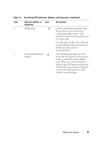
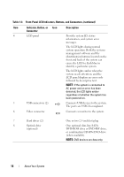
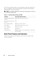
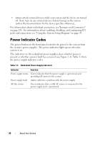
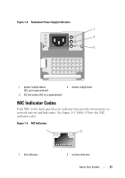
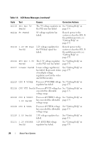
• Always attach external devices while your system and the device are turned off. Next, turn on any external devices before turning on the system (unless the documentation for the device specifies otherwise). For information about individual connectors, see "Jumpers and Connectors" on page 165. For information about enabling, disabling, and configuring I/O ports and connectors, see "Using the System Setup Program" on page 47. Power Indicator Codes The power button on the front panel controls the power to the system from the system's power supplies. The power indicator lights green when the system is on. The indicators on the redundant power supplies show whether power is present or whether a power fault has occurred (see Figure 1-4). Table 1-4 lists the power supply indicator codes. Table 1-4. Redundant Power Supply Indicators Indicator Function Power supply status Green indicates that the power supply is operational and providing DC power to the system. Power supply fault Amber indicates a problem with the power supply. AC line status Green indicates that a valid AC source is connected to the power supply and is operational. 20 About Your System
-
 1
1 -
2
-
3
-
4
-
5
-
6
-
7
-
8
-
9
-
10
-
11
-
12
-
13
-
14
-
 15
15 -
 16
16 -
 17
17 -
 18
18 -
 19
19 -
 20
20 -
 21
21 -
 22
22 -
 23
23 -
 24
24 -
 25
25 -
26
-
27
-
28
-
29
-
30
-
31
-
32
-
33
-
34
-
35
-
36
-
37
-
38
-
39
-
40
-
41
-
42
-
43
-
44
-
45
-
46
-
47
-
48
-
49
-
50
-
51
-
52
-
53
-
54
-
55
-
56
-
57
-
58
-
59
-
60
-
61
-
62
-
63
-
64
-
65
-
66
-
67
-
68
-
69
-
70
-
71
-
72
-
73
-
74
-
75
-
76
-
77
-
78
-
79
-
80
-
81
-
82
-
83
-
84
-
85
-
86
-
87
-
88
-
89
-
90
-
91
-
92
-
93
-
94
-
95
-
96
-
97
-
98
-
99
-
100
-
101
-
102
-
103
-
104
-
105
-
106
-
107
-
108
-
109
-
110
-
111
-
112
-
113
-
114
-
115
-
116
-
117
-
118
-
119
-
120
-
121
-
122
-
123
-
124
-
125
-
126
-
127
-
128
-
129
-
130
-
131
-
132
-
133
-
134
-
135
-
136
-
137
-
138
-
139
-
140
-
141
-
142
-
143
-
144
-
145
-
146
-
147
-
148
-
149
-
150
-
151
-
152
-
153
-
154
-
155
-
156
-
157
-
158
-
159
-
160
-
161
-
162
-
163
-
164
-
165
-
166
-
167
-
168
-
169
-
170
-
171
-
172
-
173
-
174
-
175
-
176
-
177
-
178
-
179
-
180
-
181
-
182
-
183
-
184
-
185
-
186
-
187
-
188
-
189
-
190
-
191
-
192
-
193
-
194
-
195
-
196
-
197
-
198
-
199
-
200
 |
 |
