Dell PowerEdge R805 Hardware Owner's Manual (PDF) - Page 130
Installing the SAS/SATA Backplane Board, See
 |
View all Dell PowerEdge R805 manuals
Add to My Manuals
Save this manual to your list of manuals |
Page 130 highlights
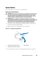
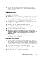
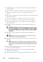
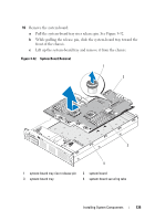
Figure 3-30. SAS/SATA Backplane Board Removal 3 2 1 4 5 6 7 1 drive carrier 3 SAS/SATA backplane board 5 optical drive power connector 7 securing tabs (7) 2 SAS backplane board release pin 4 power cable from system board 6 securing slots (7) Installing the SAS/SATA Backplane Board 1 Position the SAS/SATA backplane board so that the securing tabs on the chassis are fully inserted into the securing slots on the backplane board. See Figure 3-30. 2 Pull and hold the release pin, and then tilt the backplane board toward the front of the system until it stops, then release the release pin and ensure that it snaps into place. 3 Reinstall the sideplane board. See "Installing the Sideplane Board" on page 127. 130 Installing System Components
-
 1
1 -
2
-
3
-
4
-
5
-
6
-
7
-
8
-
9
-
10
-
11
-
12
-
13
-
14
-
15
-
16
-
17
-
18
-
19
-
20
-
21
-
22
-
23
-
24
-
25
-
26
-
27
-
28
-
29
-
30
-
31
-
32
-
33
-
34
-
35
-
36
-
37
-
38
-
39
-
40
-
41
-
42
-
43
-
44
-
45
-
46
-
47
-
48
-
49
-
50
-
51
-
52
-
53
-
54
-
55
-
56
-
57
-
58
-
59
-
60
-
61
-
62
-
63
-
64
-
65
-
66
-
67
-
68
-
69
-
70
-
71
-
72
-
73
-
74
-
75
-
76
-
77
-
78
-
79
-
80
-
81
-
82
-
83
-
84
-
85
-
86
-
87
-
88
-
89
-
90
-
91
-
92
-
93
-
94
-
95
-
96
-
97
-
98
-
99
-
100
-
101
-
102
-
103
-
104
-
105
-
106
-
107
-
108
-
109
-
110
-
111
-
112
-
113
-
114
-
115
-
116
-
117
-
118
-
119
-
120
-
121
-
122
-
123
-
124
-
 125
125 -
 126
126 -
 127
127 -
 128
128 -
 129
129 -
 130
130 -
 131
131 -
 132
132 -
 133
133 -
 134
134 -
 135
135 -
136
-
137
-
138
-
139
-
140
-
141
-
142
-
143
-
144
-
145
-
146
-
147
-
148
-
149
-
150
-
151
-
152
-
153
-
154
-
155
-
156
-
157
-
158
-
159
-
160
-
161
-
162
-
163
-
164
-
165
-
166
-
167
-
168
-
169
-
170
-
171
-
172
-
173
-
174
-
175
-
176
-
177
-
178
-
179
-
180
-
181
-
182
-
183
-
184
-
185
-
186
-
187
-
188
-
189
-
190
-
191
-
192
-
193
-
194
-
195
-
196
-
197
-
198
-
199
-
200
 |
 |

130
Installing System Components
Figure 3-30.
SAS/SATA Backplane Board Removal
Installing the SAS/SATA Backplane Board
1
Position the SAS/SATA backplane board so that the securing tabs on the
chassis are fully inserted into the securing slots on the backplane board.
See Figure 3-30.
2
Pull and hold the release pin, and then tilt the backplane board toward the
front of the system until it stops, then release the release pin and ensure
that it snaps into place.
3
Reinstall the sideplane board. See "Installing the Sideplane Board" on
page 127.
1
drive carrier
2
SAS backplane board release pin
3
SAS/SATA backplane board
4
power cable from system board
5
optical drive power connector
6
securing slots (7)
7
securing tabs (7)
1
7
3
6
2
5
4