Dell PowerEdge R805 Hardware Owner's Manual (PDF) - Page 68
Front Bezel
 |
View all Dell PowerEdge R805 manuals
Add to My Manuals
Save this manual to your list of manuals |
Page 68 highlights
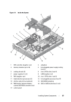
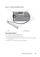
The system board holds the system's control circuitry and other electronic components. Several hardware options, such as the microprocessors and memory, are installed directly on the system board. Each expansion-card riser accommodates one full-length and one half-length PCIe expansion card. The system provides space for an optional optical drive. The optical drive connects to the SATA controller on the system board. For more information, see "Optical Drive" on page 109. The hard-drive bays provide space for up to two 2.5-inch SAS or two 2.5-inch SATA hard drives. The hard drives connect to a SAS controller card through the SAS/SATA backplane board. For more information, see "Hard Drives" on page 72 and "SAS Controller Daughter Card" on page 84. During an installation or troubleshooting procedure, you may be required to change a jumper setting. For more information, see "System Board Jumpers" on page 165. Front Bezel A lock on the bezel restricts access to the power button, optical drive, and hard drive(s). A control panel LCD located on the front panel and accessible through the front bezel displays the system's status. See Figure 3-2. 68 Installing System Components
-
 1
1 -
2
-
3
-
4
-
5
-
6
-
7
-
8
-
9
-
10
-
11
-
12
-
13
-
14
-
15
-
16
-
17
-
18
-
19
-
20
-
21
-
22
-
23
-
24
-
25
-
26
-
27
-
28
-
29
-
30
-
31
-
32
-
33
-
34
-
35
-
36
-
37
-
38
-
39
-
40
-
41
-
42
-
43
-
44
-
45
-
46
-
47
-
48
-
49
-
50
-
51
-
52
-
53
-
54
-
55
-
56
-
57
-
58
-
59
-
60
-
61
-
62
-
 63
63 -
 64
64 -
 65
65 -
 66
66 -
 67
67 -
 68
68 -
 69
69 -
 70
70 -
 71
71 -
 72
72 -
 73
73 -
74
-
75
-
76
-
77
-
78
-
79
-
80
-
81
-
82
-
83
-
84
-
85
-
86
-
87
-
88
-
89
-
90
-
91
-
92
-
93
-
94
-
95
-
96
-
97
-
98
-
99
-
100
-
101
-
102
-
103
-
104
-
105
-
106
-
107
-
108
-
109
-
110
-
111
-
112
-
113
-
114
-
115
-
116
-
117
-
118
-
119
-
120
-
121
-
122
-
123
-
124
-
125
-
126
-
127
-
128
-
129
-
130
-
131
-
132
-
133
-
134
-
135
-
136
-
137
-
138
-
139
-
140
-
141
-
142
-
143
-
144
-
145
-
146
-
147
-
148
-
149
-
150
-
151
-
152
-
153
-
154
-
155
-
156
-
157
-
158
-
159
-
160
-
161
-
162
-
163
-
164
-
165
-
166
-
167
-
168
-
169
-
170
-
171
-
172
-
173
-
174
-
175
-
176
-
177
-
178
-
179
-
180
-
181
-
182
-
183
-
184
-
185
-
186
-
187
-
188
-
189
-
190
-
191
-
192
-
193
-
194
-
195
-
196
-
197
-
198
-
199
-
200
 |
 |
