Dell PowerEdge R805 Hardware Owner's Manual (PDF) - Page 109
Replacing the LOM Daughter Card, Optical Drive, Removing the Optical Drive from the System
 |
View all Dell PowerEdge R805 manuals
Add to My Manuals
Save this manual to your list of manuals |
Page 109 highlights
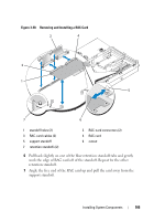
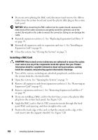
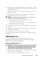
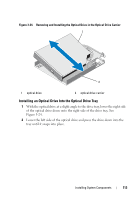
Replacing the LOM Daughter Card CAUTION: Only trained service technicians are authorized to remove the system cover and access any of the components inside the system. See your Product Information Guide for complete information about safety precautions, working inside the computer, and protecting against electrostatic discharge. 1 Angle the LOM card so that its NIC connectors are positioned toward the back-panel LOM card opening. 2 Straighten the card so that the cutouts on the side edges of the card insert into the two support standoffs. See Figure 3-21. 3 Slide the card back slightly and align the front edge of the LOM card with the two front plastic retention standoffs adjacent to the LOM system board connector, and press down the side of the card until it is fully seated. See Figure 3-20. When the front of the card is fully seated, the plastic standoff snaps over the edge of the card. 4 Reinstall all expansion cards in expansion-card riser 2. See "Installing an Expansion Card" on page 91. 5 Close the system. See "Closing the System" on page 71. Optical Drive An optional slimline DVD or CD-RW/DVD-RW optical drive is mounted on a tray that slides in the front panel and connects to the controller on the system board. NOTE: DVD devices are data only. Removing the Optical Drive from the System CAUTION: Only trained service technicians are authorized to remove the system cover and access any of the components inside the system. See your Product Information Guide for complete information about safety precautions, working inside the computer, and protecting against electrostatic discharge. 1 Turn off the system, including any attached peripherals, and disconnect the system from its electrical outlet. 2 Open the system. See "Opening the System" on page 71. 3 Disconnect the optical drive cable from the back of the optical drive tray. Installing System Components 109
-
 1
1 -
2
-
3
-
4
-
5
-
6
-
7
-
8
-
9
-
10
-
11
-
12
-
13
-
14
-
15
-
16
-
17
-
18
-
19
-
20
-
21
-
22
-
23
-
24
-
25
-
26
-
27
-
28
-
29
-
30
-
31
-
32
-
33
-
34
-
35
-
36
-
37
-
38
-
39
-
40
-
41
-
42
-
43
-
44
-
45
-
46
-
47
-
48
-
49
-
50
-
51
-
52
-
53
-
54
-
55
-
56
-
57
-
58
-
59
-
60
-
61
-
62
-
63
-
64
-
65
-
66
-
67
-
68
-
69
-
70
-
71
-
72
-
73
-
74
-
75
-
76
-
77
-
78
-
79
-
80
-
81
-
82
-
83
-
84
-
85
-
86
-
87
-
88
-
89
-
90
-
91
-
92
-
93
-
94
-
95
-
96
-
97
-
98
-
99
-
100
-
101
-
102
-
103
-
 104
104 -
 105
105 -
 106
106 -
 107
107 -
 108
108 -
 109
109 -
 110
110 -
 111
111 -
 112
112 -
 113
113 -
 114
114 -
115
-
116
-
117
-
118
-
119
-
120
-
121
-
122
-
123
-
124
-
125
-
126
-
127
-
128
-
129
-
130
-
131
-
132
-
133
-
134
-
135
-
136
-
137
-
138
-
139
-
140
-
141
-
142
-
143
-
144
-
145
-
146
-
147
-
148
-
149
-
150
-
151
-
152
-
153
-
154
-
155
-
156
-
157
-
158
-
159
-
160
-
161
-
162
-
163
-
164
-
165
-
166
-
167
-
168
-
169
-
170
-
171
-
172
-
173
-
174
-
175
-
176
-
177
-
178
-
179
-
180
-
181
-
182
-
183
-
184
-
185
-
186
-
187
-
188
-
189
-
190
-
191
-
192
-
193
-
194
-
195
-
196
-
197
-
198
-
199
-
200
 |
 |
