Dell PowerEdge R805 Hardware Owner's Manual (PDF) - Page 170
SAS/SATA Backplane Board Connectors
 |
View all Dell PowerEdge R805 manuals
Add to My Manuals
Save this manual to your list of manuals |
Page 170 highlights
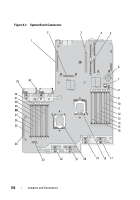
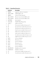
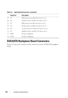
Table 6-2. System Board Connectors (continued) Connector 27 A3 28 A4 29 A5 30 A6 31 A7 32 A8 33 FAN5 34 FAN6 Description Third memory module slot (processor 1) Fourth memory module slot (processor 1) Fifth memory module slot (processor 1) Sixth memory module slot (processor 1) Seventh memory module slot (processor 1) Eighth memory module slot (processor 1) System cooling fan System cooling fan SAS/SATA Backplane Board Connectors Figure 6-3 shows the location of the connectors on the SAS/SATA backplane board. 170 Jumpers and Connectors
-
 1
1 -
2
-
3
-
4
-
5
-
6
-
7
-
8
-
9
-
10
-
11
-
12
-
13
-
14
-
15
-
16
-
17
-
18
-
19
-
20
-
21
-
22
-
23
-
24
-
25
-
26
-
27
-
28
-
29
-
30
-
31
-
32
-
33
-
34
-
35
-
36
-
37
-
38
-
39
-
40
-
41
-
42
-
43
-
44
-
45
-
46
-
47
-
48
-
49
-
50
-
51
-
52
-
53
-
54
-
55
-
56
-
57
-
58
-
59
-
60
-
61
-
62
-
63
-
64
-
65
-
66
-
67
-
68
-
69
-
70
-
71
-
72
-
73
-
74
-
75
-
76
-
77
-
78
-
79
-
80
-
81
-
82
-
83
-
84
-
85
-
86
-
87
-
88
-
89
-
90
-
91
-
92
-
93
-
94
-
95
-
96
-
97
-
98
-
99
-
100
-
101
-
102
-
103
-
104
-
105
-
106
-
107
-
108
-
109
-
110
-
111
-
112
-
113
-
114
-
115
-
116
-
117
-
118
-
119
-
120
-
121
-
122
-
123
-
124
-
125
-
126
-
127
-
128
-
129
-
130
-
131
-
132
-
133
-
134
-
135
-
136
-
137
-
138
-
139
-
140
-
141
-
142
-
143
-
144
-
145
-
146
-
147
-
148
-
149
-
150
-
151
-
152
-
153
-
154
-
155
-
156
-
157
-
158
-
159
-
160
-
161
-
162
-
163
-
164
-
 165
165 -
 166
166 -
 167
167 -
 168
168 -
 169
169 -
 170
170 -
 171
171 -
 172
172 -
 173
173 -
 174
174 -
 175
175 -
176
-
177
-
178
-
179
-
180
-
181
-
182
-
183
-
184
-
185
-
186
-
187
-
188
-
189
-
190
-
191
-
192
-
193
-
194
-
195
-
196
-
197
-
198
-
199
-
200
 |
 |

170
Jumpers and Connectors
SAS/SATA Backplane Board Connectors
Figure 6-3 shows the location of the connectors on the SAS/SATA backplane
board.
27
A3
Third memory module slot (processor 1)
28
A4
Fourth memory module slot (processor 1)
29
A5
Fifth memory module slot (processor 1)
30
A6
Sixth memory module slot (processor 1)
31
A7
Seventh memory module slot (processor 1)
32
A8
Eighth memory module slot (processor 1)
33
FAN5
System cooling fan
34
FAN6
System cooling fan
Table 6-2.
System Board Connectors
(continued)
Connector
Description