Dell PowerEdge R805 Hardware Owner's Manual (PDF) - Page 112
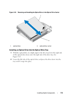
Removing the Optical Drive From the Optical Drive Tray
 |
View all Dell PowerEdge R805 manuals
Add to My Manuals
Save this manual to your list of manuals |
Page 112 highlights
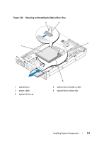
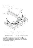
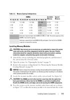
Figure 3-23. Cabling the Optical Drive 2 1 3 4 5 6 1 SATA connector (SATA_A) on system 2 SATA interface cable board 3 routing tabs in chassis side wall 4 optical-drive SATA connector 5 optical drive power cable 6 CD_PWR connector on backplane Removing the Optical Drive From the Optical Drive Tray Pull outward on the tab at the back of the carrier on the left side and simultaneously pull up on the left side of the optical drive to separate the drive from the tray. See Figure 3-24. 112 Installing System Components
-
 1
1 -
2
-
3
-
4
-
5
-
6
-
7
-
8
-
9
-
10
-
11
-
12
-
13
-
14
-
15
-
16
-
17
-
18
-
19
-
20
-
21
-
22
-
23
-
24
-
25
-
26
-
27
-
28
-
29
-
30
-
31
-
32
-
33
-
34
-
35
-
36
-
37
-
38
-
39
-
40
-
41
-
42
-
43
-
44
-
45
-
46
-
47
-
48
-
49
-
50
-
51
-
52
-
53
-
54
-
55
-
56
-
57
-
58
-
59
-
60
-
61
-
62
-
63
-
64
-
65
-
66
-
67
-
68
-
69
-
70
-
71
-
72
-
73
-
74
-
75
-
76
-
77
-
78
-
79
-
80
-
81
-
82
-
83
-
84
-
85
-
86
-
87
-
88
-
89
-
90
-
91
-
92
-
93
-
94
-
95
-
96
-
97
-
98
-
99
-
100
-
101
-
102
-
103
-
104
-
105
-
106
-
 107
107 -
 108
108 -
 109
109 -
 110
110 -
 111
111 -
 112
112 -
 113
113 -
 114
114 -
 115
115 -
 116
116 -
 117
117 -
118
-
119
-
120
-
121
-
122
-
123
-
124
-
125
-
126
-
127
-
128
-
129
-
130
-
131
-
132
-
133
-
134
-
135
-
136
-
137
-
138
-
139
-
140
-
141
-
142
-
143
-
144
-
145
-
146
-
147
-
148
-
149
-
150
-
151
-
152
-
153
-
154
-
155
-
156
-
157
-
158
-
159
-
160
-
161
-
162
-
163
-
164
-
165
-
166
-
167
-
168
-
169
-
170
-
171
-
172
-
173
-
174
-
175
-
176
-
177
-
178
-
179
-
180
-
181
-
182
-
183
-
184
-
185
-
186
-
187
-
188
-
189
-
190
-
191
-
192
-
193
-
194
-
195
-
196
-
197
-
198
-
199
-
200
 |
 |

112
Installing System Components
Figure 3-23.
Cabling the Optical Drive
Removing the Optical Drive From the Optical Drive Tray
Pull outward on the tab at the back of the carrier on the left side and
simultaneously pull up on the left side of the optical drive to separate the
drive from the tray. See Figure 3-24.
1
SATA connector (SATA_A) on system
board
2
SATA interface cable
3
routing tabs in chassis side wall
4
optical-drive SATA connector
5
optical drive power cable
6
CD_PWR connector on backplane
4
1
3
2
5
6