Dell PowerEdge R805 Hardware Owner's Manual (PDF) - Page 134
Remove the cooling shrouds. See Removing the Memory Module Cooling
 |
View all Dell PowerEdge R805 manuals
Add to My Manuals
Save this manual to your list of manuals |
Page 134 highlights
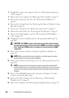
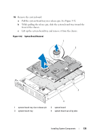
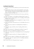
3 If applicable, remove any expansion cards. See "Removing an Expansion Card" on page 92. 4 Remove the power supplies. See "Removing a Power Supply" on page 78. 5 Remove the expansion-card risers. See "Expansion-Card Risers" on page 99. 6 Remove the cooling shrouds. See "Removing the Memory Module Cooling Shrouds" on page 94. 7 Remove the cooling fans. See "Removing a System Fan" on page 82. 8 Remove the fan brackets. See "Removing the Fan Brackets" on page 97. 9 Remove the LOM daughter card. See "Removing the LOM Daughter Card" on page 107. 10 If applicable, remove the RAC card. See "Removing the RAC Card" on page 104. CAUTION: The DIMMs are hot to the touch for some time after the system has been powered down. Allow time for the DIMMs to cool before handling them. Handle the DIMMs by the card edges and avoid touching the DIMM components. 11 Remove the memory modules. See "Removing Memory Modules" on page 119. NOTE: While removing the memory modules, record the memory module socket locations to ensure proper installation. 12 Remove the heatsinks and microprocessors. See "Removing a Processor" on page 120. NOTE: If the board is to be returned for repair, remove the protective ZIF socket shields from the new system board and install them over the processor sockets on the removed system board to prevent damage to the pins during shipping. 13 Remove the LOM NIC hardware key, if present. See Figure 6-2 for the location of the TOE_KEY socket. 14 Remove the SAS controller card. See "Removing a SAS Controller Daughter Card" on page 86. 15 Remove the sideplane. See "Removing the Sideplane Board" on page 127. 134 Installing System Components
-
 1
1 -
2
-
3
-
4
-
5
-
6
-
7
-
8
-
9
-
10
-
11
-
12
-
13
-
14
-
15
-
16
-
17
-
18
-
19
-
20
-
21
-
22
-
23
-
24
-
25
-
26
-
27
-
28
-
29
-
30
-
31
-
32
-
33
-
34
-
35
-
36
-
37
-
38
-
39
-
40
-
41
-
42
-
43
-
44
-
45
-
46
-
47
-
48
-
49
-
50
-
51
-
52
-
53
-
54
-
55
-
56
-
57
-
58
-
59
-
60
-
61
-
62
-
63
-
64
-
65
-
66
-
67
-
68
-
69
-
70
-
71
-
72
-
73
-
74
-
75
-
76
-
77
-
78
-
79
-
80
-
81
-
82
-
83
-
84
-
85
-
86
-
87
-
88
-
89
-
90
-
91
-
92
-
93
-
94
-
95
-
96
-
97
-
98
-
99
-
100
-
101
-
102
-
103
-
104
-
105
-
106
-
107
-
108
-
109
-
110
-
111
-
112
-
113
-
114
-
115
-
116
-
117
-
118
-
119
-
120
-
121
-
122
-
123
-
124
-
125
-
126
-
127
-
128
-
 129
129 -
 130
130 -
 131
131 -
 132
132 -
 133
133 -
 134
134 -
 135
135 -
 136
136 -
 137
137 -
 138
138 -
 139
139 -
140
-
141
-
142
-
143
-
144
-
145
-
146
-
147
-
148
-
149
-
150
-
151
-
152
-
153
-
154
-
155
-
156
-
157
-
158
-
159
-
160
-
161
-
162
-
163
-
164
-
165
-
166
-
167
-
168
-
169
-
170
-
171
-
172
-
173
-
174
-
175
-
176
-
177
-
178
-
179
-
180
-
181
-
182
-
183
-
184
-
185
-
186
-
187
-
188
-
189
-
190
-
191
-
192
-
193
-
194
-
195
-
196
-
197
-
198
-
199
-
200
 |
 |
