Dell PowerEdge R805 Hardware Owner's Manual (PDF) - Page 19
Connecting External Devices, When connecting external devices to your system, follow these guidelines
 |
View all Dell PowerEdge R805 manuals
Add to My Manuals
Save this manual to your list of manuals |
Page 19 highlights
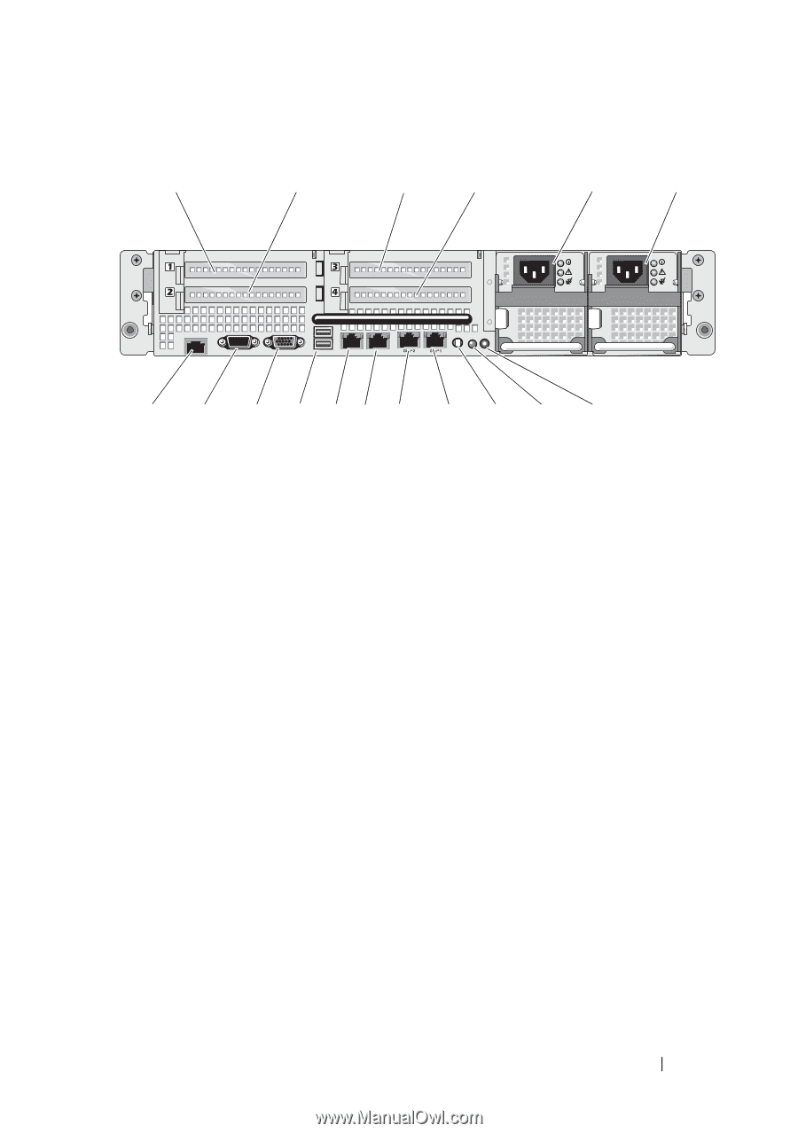
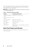
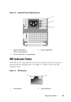
Figure 1-3. Back-Panel Features and Indicators 1 2 3 4 5 6 17 16 15 14 13 12 11 10 9 8 7 1 PCIe slot 1 3 PCIe slot 3 5 power supply bay 1 (PS1) 7 system identification button 9 system status indicator connector 11 LOM3 connector (Gb/10Gb)a 13 LOM1 connector (Gb) 15 video connector 17 remote access controller (RAC) connector (optional) a. Upgradeable to 10Gbps when available 2 PCIe slot 2 4 PCIe slot 4 6 power supply bay 2 (PS2) 8 system status indicator 10 LOM4 connector (Gb/10Gb)a 12 LOM2 connector (Gb) 14 2.0-compliant USB connectors (2) 16 serial connector Connecting External Devices When connecting external devices to your system, follow these guidelines: • Most devices must be connected to a specific connector and device drivers must be installed before the device operates properly. (Device drivers are normally included with your operating system software or with the device itself.) See the documentation that accompanied the device for specific installation and configuration instructions. About Your System 19
-
 1
1 -
2
-
3
-
4
-
5
-
6
-
7
-
8
-
9
-
10
-
11
-
12
-
13
-
 14
14 -
 15
15 -
 16
16 -
 17
17 -
 18
18 -
 19
19 -
 20
20 -
 21
21 -
 22
22 -
 23
23 -
 24
24 -
25
-
26
-
27
-
28
-
29
-
30
-
31
-
32
-
33
-
34
-
35
-
36
-
37
-
38
-
39
-
40
-
41
-
42
-
43
-
44
-
45
-
46
-
47
-
48
-
49
-
50
-
51
-
52
-
53
-
54
-
55
-
56
-
57
-
58
-
59
-
60
-
61
-
62
-
63
-
64
-
65
-
66
-
67
-
68
-
69
-
70
-
71
-
72
-
73
-
74
-
75
-
76
-
77
-
78
-
79
-
80
-
81
-
82
-
83
-
84
-
85
-
86
-
87
-
88
-
89
-
90
-
91
-
92
-
93
-
94
-
95
-
96
-
97
-
98
-
99
-
100
-
101
-
102
-
103
-
104
-
105
-
106
-
107
-
108
-
109
-
110
-
111
-
112
-
113
-
114
-
115
-
116
-
117
-
118
-
119
-
120
-
121
-
122
-
123
-
124
-
125
-
126
-
127
-
128
-
129
-
130
-
131
-
132
-
133
-
134
-
135
-
136
-
137
-
138
-
139
-
140
-
141
-
142
-
143
-
144
-
145
-
146
-
147
-
148
-
149
-
150
-
151
-
152
-
153
-
154
-
155
-
156
-
157
-
158
-
159
-
160
-
161
-
162
-
163
-
164
-
165
-
166
-
167
-
168
-
169
-
170
-
171
-
172
-
173
-
174
-
175
-
176
-
177
-
178
-
179
-
180
-
181
-
182
-
183
-
184
-
185
-
186
-
187
-
188
-
189
-
190
-
191
-
192
-
193
-
194
-
195
-
196
-
197
-
198
-
199
-
200
 |
 |