Dell PowerEdge R805 Hardware Owner's Manual (PDF) - Page 129
SAS/SATA Backplane Board, Removing the SAS/SATA Backplane Board
 |
View all Dell PowerEdge R805 manuals
Add to My Manuals
Save this manual to your list of manuals |
Page 129 highlights
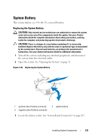
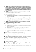
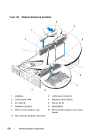
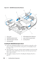
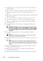
SAS/SATA Backplane Board Removing the SAS/SATA Backplane Board CAUTION: Only trained service technicians are authorized to remove the system cover and access any of the components inside the system. See your Product Information Guide for complete information about safety precautions, working inside the computer, and protecting against electrostatic discharge. 1 Turn off the system and attached peripherals, and disconnect the system from the electrical outlet. 2 Open the system. See "Opening the System" on page 71. 3 If present, disconnect the optical drive power cable from the SAS/SATA backplane board. See "Removing the Optical Drive from the System" on page 109. 4 Open the drive-carrier release handle on each hard drive and partially extend the drive(s) out of their drive bays. See "Removing a Hot-Plug Hard Drive" on page 74. 5 Remove the storage controller daughter card. See "Removing a SAS Controller Daughter Card" on page 86. 6 Disconnect the SAS cable from the backplane connector. 7 Disconnect the power cable from the backplane connector. 8 Disconnect the optical drive power cable from the backplane connector. 9 Remove the sideplane board. See "Removing the Sideplane Board" on page 127. 10 Remove the SAS/SATA backplane board: a Pull the backplane board release pin. See Figure 3-30. b While pulling the release pin, tilt the backplane board toward the back of the system. c Lift the backplane board from its securing tabs and remove the backplane board from the chassis. Installing System Components 129
-
 1
1 -
2
-
3
-
4
-
5
-
6
-
7
-
8
-
9
-
10
-
11
-
12
-
13
-
14
-
15
-
16
-
17
-
18
-
19
-
20
-
21
-
22
-
23
-
24
-
25
-
26
-
27
-
28
-
29
-
30
-
31
-
32
-
33
-
34
-
35
-
36
-
37
-
38
-
39
-
40
-
41
-
42
-
43
-
44
-
45
-
46
-
47
-
48
-
49
-
50
-
51
-
52
-
53
-
54
-
55
-
56
-
57
-
58
-
59
-
60
-
61
-
62
-
63
-
64
-
65
-
66
-
67
-
68
-
69
-
70
-
71
-
72
-
73
-
74
-
75
-
76
-
77
-
78
-
79
-
80
-
81
-
82
-
83
-
84
-
85
-
86
-
87
-
88
-
89
-
90
-
91
-
92
-
93
-
94
-
95
-
96
-
97
-
98
-
99
-
100
-
101
-
102
-
103
-
104
-
105
-
106
-
107
-
108
-
109
-
110
-
111
-
112
-
113
-
114
-
115
-
116
-
117
-
118
-
119
-
120
-
121
-
122
-
123
-
 124
124 -
 125
125 -
 126
126 -
 127
127 -
 128
128 -
 129
129 -
 130
130 -
 131
131 -
 132
132 -
 133
133 -
 134
134 -
135
-
136
-
137
-
138
-
139
-
140
-
141
-
142
-
143
-
144
-
145
-
146
-
147
-
148
-
149
-
150
-
151
-
152
-
153
-
154
-
155
-
156
-
157
-
158
-
159
-
160
-
161
-
162
-
163
-
164
-
165
-
166
-
167
-
168
-
169
-
170
-
171
-
172
-
173
-
174
-
175
-
176
-
177
-
178
-
179
-
180
-
181
-
182
-
183
-
184
-
185
-
186
-
187
-
188
-
189
-
190
-
191
-
192
-
193
-
194
-
195
-
196
-
197
-
198
-
199
-
200
 |
 |
