Epson 680Pro Service Manual - Page 101
Overview, 5.1.1 Required Adjustment, EPSON Stylus COLOR 680/777/777i, Revision B, Adjustment
 |
UPC - 010343832138
View all Epson 680Pro manuals
Add to My Manuals
Save this manual to your list of manuals |
Page 101 highlights
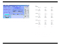
EPSON Stylus COLOR 680/777/777i Revision B 5.1 Overview This section describes the procedure for adjustments required when the printer is disassembled and assembled for repair or service. 5.1.1 Required Adjustment Table 5-1 lists all the necessary adjustments for this printer. If any service listed in this table is carried out, all adjustments corresponding to that service item should be performed to ensure proper operation of the printer. Table 5-1. Required Adjustment 1 2 3 4 5 Service item Printhead removal Head ID input NA Ink Change NA Bi-D Adjustme nt Q USB ID input NA Protection Counter reset NA Printhead replacement Q R S NA NA Main board replacement Q NA R S NA CR Unit replacement or removal NA NA Q NA NA CR Motor replacement NA NA Q NA NA Printer mechanism Q replacement R S NA NA Waste Ink pad replacement NA NA NA NA Q ¡ NOTE: " ": Required Adjustment. The number in the circle shows the required adjustment order. "NA": Not applicable. NOTE: Following adjustments are not required on this product. - Platen Gap adjustment - Head Angular adjustment. This section describes the detailed procedures of each adjustment by Adjustment Program. In this printer, it is necessary to set the adjusting information for each printer mechanism in order to maintain consistent printing function and quality, eliminating differences of each printer mechanism's characteristics. Therefore, in case that the combination of the printer mechanism and main board changes or the print head is replaced during the repair service, you must set and save the correct information to the MAIN board, using the exclusive adjustment program. This section describes the detailed procedures of each adjustment by Adjustment Program. CHECK P O IN T In case any parts is removed and assembled on the repair product while running the Adjustment program, turn off the printer certainly. Adjustment Overview 101
-
 1
1 -
2
-
3
-
4
-
5
-
6
-
7
-
8
-
9
-
10
-
11
-
12
-
13
-
14
-
15
-
16
-
17
-
18
-
19
-
20
-
21
-
22
-
23
-
24
-
25
-
26
-
27
-
28
-
29
-
30
-
31
-
32
-
33
-
34
-
35
-
36
-
37
-
38
-
39
-
40
-
41
-
42
-
43
-
44
-
45
-
46
-
47
-
48
-
49
-
50
-
51
-
52
-
53
-
54
-
55
-
56
-
57
-
58
-
59
-
60
-
61
-
62
-
63
-
64
-
65
-
66
-
67
-
68
-
69
-
70
-
71
-
72
-
73
-
74
-
75
-
76
-
77
-
78
-
79
-
80
-
81
-
82
-
83
-
84
-
85
-
86
-
87
-
88
-
89
-
90
-
91
-
92
-
93
-
94
-
95
-
 96
96 -
 97
97 -
 98
98 -
 99
99 -
 100
100 -
 101
101 -
 102
102 -
 103
103 -
 104
104 -
 105
105 -
 106
106 -
107
-
108
-
109
-
110
-
111
-
112
-
113
-
114
-
115
-
116
-
117
-
118
-
119
-
120
-
121
-
122
-
123
-
124
-
125
-
126
-
127
-
128
-
129
-
130
-
131
-
132
-
133
-
134
-
135
-
136
-
137
-
138
-
139
-
140
-
141
-
142
-
143
-
144
-
145
 |
 |