Epson 680Pro Service Manual - Page 37
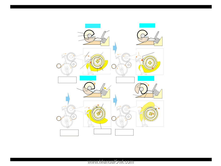
ASF Paper Loading Sequence, Step 1, ASF hopper, release lever
 |
UPC - 010343832138
View all Epson 680Pro manuals
Add to My Manuals
Save this manual to your list of manuals |
Page 37 highlights
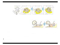
EPSON Stylus COLOR 680/777/77i Revision B When the paper is advanced with the PF roller, Change lever push down the Clutch lever as right figure and the Clutch lock tooth is disengaged from the Clutch gear. As the result, the drive from the PF motor is interrupted and the LD roller dose not rotate. This position is the ASF home position. The Paper return plate is set to avoid that the paper is slipped down from the paper set position. The PF motor pinion gear rotates CW direction and the drive from the PF motor is transmitted to the ASF LD roller shaft through the Clutch lock tooth and the Clutch gear. The ASF hopper release lever rotates with the ASF LD roller and release the ASF Hopper. The ASF hopper is pushed with the Compression spring 4.80 and the paper is picked up with the ASF LD roller. LD roller LD roller shaft Paper return plate Step 1 Hopper Change lever Clutch gear Step 2 Printer front side Tension spring 0.143 When the paper is loaded (pick up) from the ASF unit, the Change lever moves to the printer front side with the CCW rotation of the PF motor pinion gear and releases the Clutch lever. As the result, the Clutch turns back to the engagement position by the tension force of the Tension spring 0.143. And the Clutch lock tooth is engaged with the Clutch gear as right figure. Clutch lever Clutch lock tooth Clutch PF motor pinion gear CW rotation ASF Hopper release lever Step 3 PF motor pinion gear CCW rotation Compression spring 4.80 Step 4 LD roller shaft ASF Frame Paper return plate The ASF LD roller rotates CW direction moreover and the Paper return plate is stored under the ASF frame. The paper is advanced up to the PF roller. and the ASF LD roller & the clutch rotate to the "Step1" position. The Clutch lever is locked with the Change lever. The drive from the PF motor is interrupted and the drive is transmitted to the PF roller side. PF motor pinion gear CW rotation ASF hopper release lever PF motor pinion gear CW rotation Figure 2-11. ASF Paper Loading Sequence Operating Principles Overview 37
-
 1
1 -
2
-
3
-
4
-
5
-
6
-
7
-
8
-
9
-
10
-
11
-
12
-
13
-
14
-
15
-
16
-
17
-
18
-
19
-
20
-
21
-
22
-
23
-
24
-
25
-
26
-
27
-
28
-
29
-
30
-
31
-
 32
32 -
 33
33 -
 34
34 -
 35
35 -
 36
36 -
 37
37 -
 38
38 -
 39
39 -
 40
40 -
 41
41 -
 42
42 -
43
-
44
-
45
-
46
-
47
-
48
-
49
-
50
-
51
-
52
-
53
-
54
-
55
-
56
-
57
-
58
-
59
-
60
-
61
-
62
-
63
-
64
-
65
-
66
-
67
-
68
-
69
-
70
-
71
-
72
-
73
-
74
-
75
-
76
-
77
-
78
-
79
-
80
-
81
-
82
-
83
-
84
-
85
-
86
-
87
-
88
-
89
-
90
-
91
-
92
-
93
-
94
-
95
-
96
-
97
-
98
-
99
-
100
-
101
-
102
-
103
-
104
-
105
-
106
-
107
-
108
-
109
-
110
-
111
-
112
-
113
-
114
-
115
-
116
-
117
-
118
-
119
-
120
-
121
-
122
-
123
-
124
-
125
-
126
-
127
-
128
-
129
-
130
-
131
-
132
-
133
-
134
-
135
-
136
-
137
-
138
-
139
-
140
-
141
-
142
-
143
-
144
-
145
 |
 |