Epson 680Pro Service Manual - Page 74
Drain ink tube setting position, drain ink pad. Refer to
 |
UPC - 010343832138
View all Epson 680Pro manuals
Add to My Manuals
Save this manual to your list of manuals |
Page 74 highlights
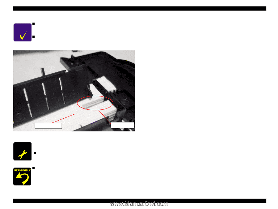
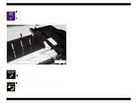
EPSON Stylus COLOR 680/777/777i CHECK P O IN T . n After assembling the Waste drain ink pad unit, be sure to set the some cables in the cable hook in the Waste drain ink pad unit. n Refer to the Figure 4-13. When assembling the Waste drain ink pad unit, be sure to set the tip of the waste ink tube in the suitable position of the Waste drain ink pad. Refer to the Figure 4-14. Waste drain ink pad Ink tube Figure 4-14. Drain ink tube setting position A D JU S TM E N T R E Q U IR E D When the Waste drain ink pad is replaced with a new one, nfollowing service item is required. Waste drain ink counter reset operation. n Tightening torque for screw • C.B.P-TITE 3x8 screw for Waste drain ink pad unit : 9+/1 kgf.cm Disassembly and Assembly Disassembly Revision B 74
-
 1
1 -
2
-
3
-
4
-
5
-
6
-
7
-
8
-
9
-
10
-
11
-
12
-
13
-
14
-
15
-
16
-
17
-
18
-
19
-
20
-
21
-
22
-
23
-
24
-
25
-
26
-
27
-
28
-
29
-
30
-
31
-
32
-
33
-
34
-
35
-
36
-
37
-
38
-
39
-
40
-
41
-
42
-
43
-
44
-
45
-
46
-
47
-
48
-
49
-
50
-
51
-
52
-
53
-
54
-
55
-
56
-
57
-
58
-
59
-
60
-
61
-
62
-
63
-
64
-
65
-
66
-
67
-
68
-
 69
69 -
 70
70 -
 71
71 -
 72
72 -
 73
73 -
 74
74 -
 75
75 -
 76
76 -
 77
77 -
 78
78 -
 79
79 -
80
-
81
-
82
-
83
-
84
-
85
-
86
-
87
-
88
-
89
-
90
-
91
-
92
-
93
-
94
-
95
-
96
-
97
-
98
-
99
-
100
-
101
-
102
-
103
-
104
-
105
-
106
-
107
-
108
-
109
-
110
-
111
-
112
-
113
-
114
-
115
-
116
-
117
-
118
-
119
-
120
-
121
-
122
-
123
-
124
-
125
-
126
-
127
-
128
-
129
-
130
-
131
-
132
-
133
-
134
-
135
-
136
-
137
-
138
-
139
-
140
-
141
-
142
-
143
-
144
-
145
 |
 |