Epson 680Pro Service Manual - Page 40
Electrical Circuit Operating Principles, 2.2.1 C383 PSB/PSE board
 |
UPC - 010343832138
View all Epson 680Pro manuals
Add to My Manuals
Save this manual to your list of manuals |
Page 40 highlights
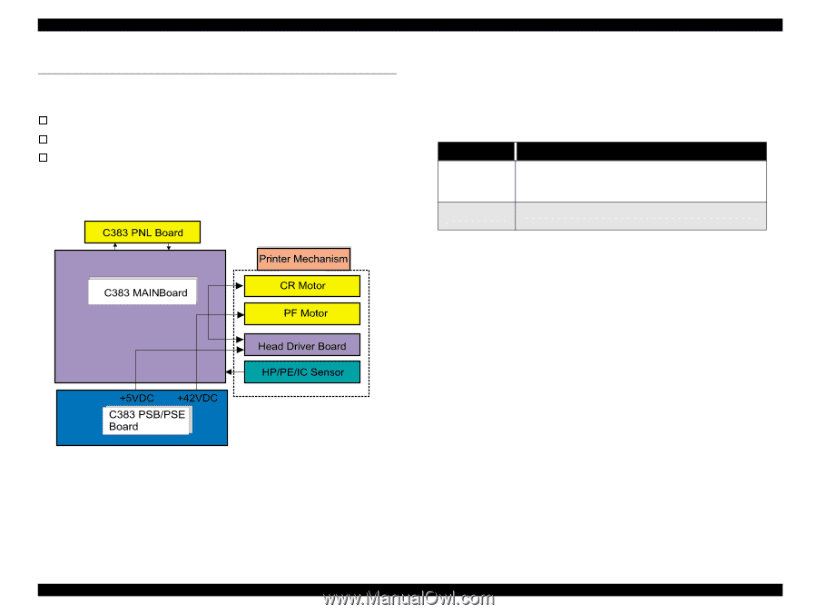
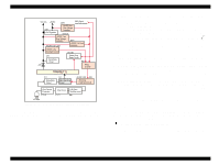
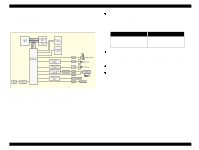
EPSON Stylus COLOR 680/777/77i 2.2 Electrical Circuit Operating Principles The electric circuit of the Stylus COLOR 680/777/777i consists of the following boards. o Main board: C383 MAIN Board o Power supply board: C383 PSB/PSE Board o Panel board: C383 PNL Board This section provides operating principles of C383 Board and C383 PSB/PSE Board. Refer to Figure 2-15 for the major connection of the each boards and their roles. Revision B 2.2.1 C383 PSB/PSE board The power supply boards of Stylus COLOR 680/777/777i use a RCC (Ringing Chalk Converter) circuit, which generates +42VDC for drive line and +5VDC for logic line to drive the printer. The application of the output voltage is described below. Table 2-5. Application of the DC Voltages Voltage Application +42VDC +5VDC • Motors (CR Motor, PF Motor) • Printhead common voltage • Printhead nozzle selector 42V drive voltage • C383MAIN control circuit logic • Sensor AC voltage input from AC inlet first goes through filter circuit that removes high frequency components and is then converted to DC voltage via the rectifier circuit and the smoothing circuit. DC voltage is then lead to the switching circuit and FET Q1 preforms the switching operation. By the switching operation of the primary circuit, +42VDC is generated and stabilized at the secondary circuit. This +42VDC generated by the secondary circuit is converted to +5VDC by the chopping regulator IC of the secondary circuit. Figure 2-15. Electric Circuit Operating Principles Electrical Circuit Operating Principles 40
-
 1
1 -
2
-
3
-
4
-
5
-
6
-
7
-
8
-
9
-
10
-
11
-
12
-
13
-
14
-
15
-
16
-
17
-
18
-
19
-
20
-
21
-
22
-
23
-
24
-
25
-
26
-
27
-
28
-
29
-
30
-
31
-
32
-
33
-
34
-
 35
35 -
 36
36 -
 37
37 -
 38
38 -
 39
39 -
 40
40 -
 41
41 -
 42
42 -
 43
43 -
 44
44 -
 45
45 -
46
-
47
-
48
-
49
-
50
-
51
-
52
-
53
-
54
-
55
-
56
-
57
-
58
-
59
-
60
-
61
-
62
-
63
-
64
-
65
-
66
-
67
-
68
-
69
-
70
-
71
-
72
-
73
-
74
-
75
-
76
-
77
-
78
-
79
-
80
-
81
-
82
-
83
-
84
-
85
-
86
-
87
-
88
-
89
-
90
-
91
-
92
-
93
-
94
-
95
-
96
-
97
-
98
-
99
-
100
-
101
-
102
-
103
-
104
-
105
-
106
-
107
-
108
-
109
-
110
-
111
-
112
-
113
-
114
-
115
-
116
-
117
-
118
-
119
-
120
-
121
-
122
-
123
-
124
-
125
-
126
-
127
-
128
-
129
-
130
-
131
-
132
-
133
-
134
-
135
-
136
-
137
-
138
-
139
-
140
-
141
-
142
-
143
-
144
-
145
 |
 |