Epson 680Pro Service Manual - Page 86
Gear engagement on the Ink system frame, Ink tube placing position
 |
UPC - 010343832138
View all Epson 680Pro manuals
Add to My Manuals
Save this manual to your list of manuals |
Page 86 highlights
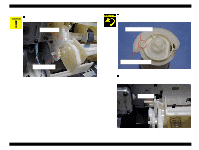
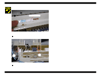
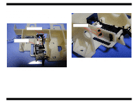
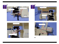
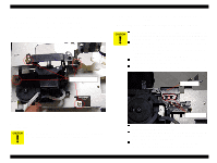
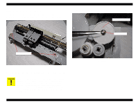
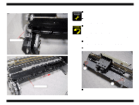
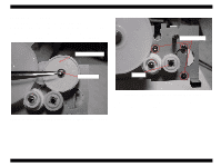
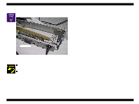
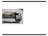
EPSON Stylus COLOR 680/777/777i CHECK P O IN T n Make sure that all gears are set in each gear shaft on the Ink system frame. Combination gear 9.6, 24 Combination gear 37.6, 44.4 Figure 4-36. Gear engagement on the Ink system frame n Make sure that the ink tube is placed along the following position. Pump unit Cap assembly Ink tube Revision B n Tightening torque for screw • C.B.S 3x6 F/Zn screw for Ink system frame & Cap assy.: 9+/1 kgf.cm Figure 4-37. Ink tube placing position n After installing the Pump Assembly, ensure that the cleaner parts move back and forth by rotating the Gear. Disassembly and Assembly Disassembly 86
-
 1
1 -
2
-
3
-
4
-
5
-
6
-
7
-
8
-
9
-
10
-
11
-
12
-
13
-
14
-
15
-
16
-
17
-
18
-
19
-
20
-
21
-
22
-
23
-
24
-
25
-
26
-
27
-
28
-
29
-
30
-
31
-
32
-
33
-
34
-
35
-
36
-
37
-
38
-
39
-
40
-
41
-
42
-
43
-
44
-
45
-
46
-
47
-
48
-
49
-
50
-
51
-
52
-
53
-
54
-
55
-
56
-
57
-
58
-
59
-
60
-
61
-
62
-
63
-
64
-
65
-
66
-
67
-
68
-
69
-
70
-
71
-
72
-
73
-
74
-
75
-
76
-
77
-
78
-
79
-
80
-
 81
81 -
 82
82 -
 83
83 -
 84
84 -
 85
85 -
 86
86 -
 87
87 -
 88
88 -
 89
89 -
 90
90 -
 91
91 -
92
-
93
-
94
-
95
-
96
-
97
-
98
-
99
-
100
-
101
-
102
-
103
-
104
-
105
-
106
-
107
-
108
-
109
-
110
-
111
-
112
-
113
-
114
-
115
-
116
-
117
-
118
-
119
-
120
-
121
-
122
-
123
-
124
-
125
-
126
-
127
-
128
-
129
-
130
-
131
-
132
-
133
-
134
-
135
-
136
-
137
-
138
-
139
-
140
-
141
-
142
-
143
-
144
-
145
 |
 |

EPSON Stylus COLOR 680/777/777i
Revision B
Disassembly and Assembly
Disassembly
86
C
H
E
C
K
P
O
I
N
T
Make sure that all gears are set in each gear shaft on the Ink
system frame.
Figure 4-36. Gear engagement on the Ink system frame
Make sure that the ink tube is placed along the following
position.
Figure 4-37. Ink tube placing position
After installing the Pump Assembly, ensure that the cleaner
parts move back and forth by rotating the Gear.
Combination gear
37.6, 44.4
Combination gear
9.6, 24
Cap assembly
Ink tube
Pump unit
Tightening torque for screw
•
C.B.S 3x6 F/Zn screw for Ink system frame & Cap assy.: 9+/1 kgf.cm