Epson 680Pro Service Manual - Page 81
Spur Gear 23.2 and Spur Gear 35.2, Assembling the Clutch
 |
UPC - 010343832138
View all Epson 680Pro manuals
Add to My Manuals
Save this manual to your list of manuals |
Page 81 highlights
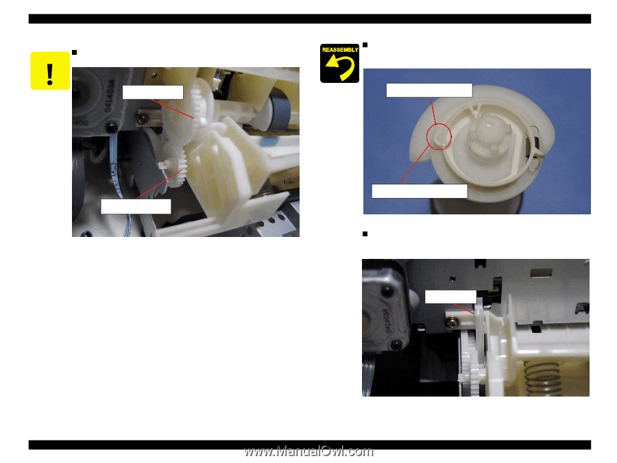
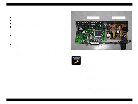
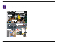
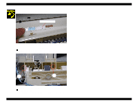
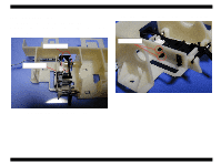
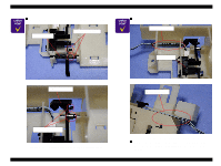
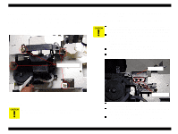
EPSON Stylus COLOR 680/777/777i n Do not damage the tooth of the Spur gear 35.2 and the Spur gear C A U T IO N 23.2 when assembling the LD roller shaft holder unit. Spur gear 35.2 Revision B n Before assembling the LD roller shaft, make sure that the round hole of the Clutch is set on the protrusion on the LD roller shaft as shown in the following figure. round hole on the Clutch Spur gear 23.2 Spur gear 23.2 Figure 4-24. Spur Gear 23.2 and Spur Gear 35.2 Protrusion on the LD roller shaft Figure 4-25. Assembling the Clutch n Assemble the LD roller shaft holder unit to the printer mechanism in the following procedure. 1) Set the tip of the Change lever to the printer front side. Change lever Disassembly and Assembly Disassembly Figure 4-26. LD Roller shaft holder assembling procedure (1) 81
-
 1
1 -
2
-
3
-
4
-
5
-
6
-
7
-
8
-
9
-
10
-
11
-
12
-
13
-
14
-
15
-
16
-
17
-
18
-
19
-
20
-
21
-
22
-
23
-
24
-
25
-
26
-
27
-
28
-
29
-
30
-
31
-
32
-
33
-
34
-
35
-
36
-
37
-
38
-
39
-
40
-
41
-
42
-
43
-
44
-
45
-
46
-
47
-
48
-
49
-
50
-
51
-
52
-
53
-
54
-
55
-
56
-
57
-
58
-
59
-
60
-
61
-
62
-
63
-
64
-
65
-
66
-
67
-
68
-
69
-
70
-
71
-
72
-
73
-
74
-
75
-
 76
76 -
 77
77 -
 78
78 -
 79
79 -
 80
80 -
 81
81 -
 82
82 -
 83
83 -
 84
84 -
 85
85 -
 86
86 -
87
-
88
-
89
-
90
-
91
-
92
-
93
-
94
-
95
-
96
-
97
-
98
-
99
-
100
-
101
-
102
-
103
-
104
-
105
-
106
-
107
-
108
-
109
-
110
-
111
-
112
-
113
-
114
-
115
-
116
-
117
-
118
-
119
-
120
-
121
-
122
-
123
-
124
-
125
-
126
-
127
-
128
-
129
-
130
-
131
-
132
-
133
-
134
-
135
-
136
-
137
-
138
-
139
-
140
-
141
-
142
-
143
-
144
-
145
 |
 |