Epson 680Pro Service Manual - Page 72
Removing the CR motor
 |
UPC - 010343832138
View all Epson 680Pro manuals
Add to My Manuals
Save this manual to your list of manuals |
Page 72 highlights
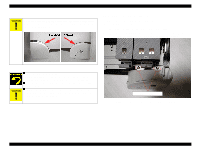
EPSON Stylus COLOR 680/777/777i 4. Remove four Hexagon Nuts while holding the CR motor and remove the CR motor assembly. Refer to Figure 4-11. Hexagon nuts Figure 4-11. Removing the CR motor 5. Take the CR motor's cable out from the cable hook in the Waste drain inkpad unit. 6. Disconnect the CR motor connector cable from the CN12 on the Main board with tweezers. n A D J U S T M E N T The Gap adjustment (Bi-d adjustment) is required when the CR R E Q U IR E D motor is removed or replaced. n Connect the CR motor connector cable to the CN12 on the Main board. Use of tweezers or pincers is recommended to facilitate the job, since the CN12 is not located near the rear edge of the Main board. Disassembly and Assembly Disassembly Revision B 72
-
 1
1 -
2
-
3
-
4
-
5
-
6
-
7
-
8
-
9
-
10
-
11
-
12
-
13
-
14
-
15
-
16
-
17
-
18
-
19
-
20
-
21
-
22
-
23
-
24
-
25
-
26
-
27
-
28
-
29
-
30
-
31
-
32
-
33
-
34
-
35
-
36
-
37
-
38
-
39
-
40
-
41
-
42
-
43
-
44
-
45
-
46
-
47
-
48
-
49
-
50
-
51
-
52
-
53
-
54
-
55
-
56
-
57
-
58
-
59
-
60
-
61
-
62
-
63
-
64
-
65
-
66
-
 67
67 -
 68
68 -
 69
69 -
 70
70 -
 71
71 -
 72
72 -
 73
73 -
 74
74 -
 75
75 -
 76
76 -
 77
77 -
78
-
79
-
80
-
81
-
82
-
83
-
84
-
85
-
86
-
87
-
88
-
89
-
90
-
91
-
92
-
93
-
94
-
95
-
96
-
97
-
98
-
99
-
100
-
101
-
102
-
103
-
104
-
105
-
106
-
107
-
108
-
109
-
110
-
111
-
112
-
113
-
114
-
115
-
116
-
117
-
118
-
119
-
120
-
121
-
122
-
123
-
124
-
125
-
126
-
127
-
128
-
129
-
130
-
131
-
132
-
133
-
134
-
135
-
136
-
137
-
138
-
139
-
140
-
141
-
142
-
143
-
144
-
145
 |
 |
EPSON Stylus COLOR 680/777/777i
Revision B
Disassembly and Assembly
Disassembly
72
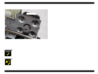
4.
Remove four Hexagon Nuts while holding the CR motor and remove the CR
motor assembly. Refer to Figure 4-11.
Figure 4-11. Removing the CR motor
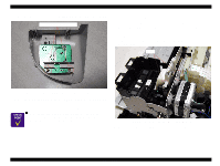
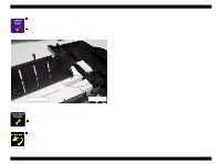
5.
Take the CR motor's cable out from the cable hook in the Waste drain inkpad unit.
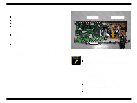
6.
Disconnect the CR motor connector cable from the CN12 on the Main board with
tweezers.
A
D
J
U
S
T
M
E
N
T
R
E
Q
U
I
R
E
D
The Gap adjustment (Bi-d adjustment) is required when the CR
motor is removed or replaced.
Connect the CR motor connector cable to the CN12 on the Main
board. Use of tweezers or pincers is recommended to facilitate
the job, since the CN12 is not located near the rear edge of the
Main board.
Hexagon nuts