Epson 680Pro Service Manual - Page 88
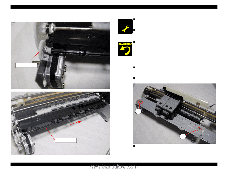
Fasten the Front frame with C.B.S Screw 3x6 F/Zn in the order, Refer to
 |
UPC - 010343832138
View all Epson 680Pro manuals
Add to My Manuals
Save this manual to your list of manuals |
Page 88 highlights
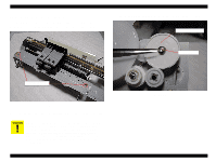
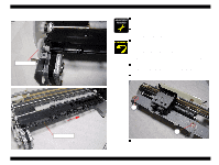
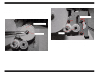
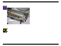
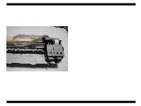
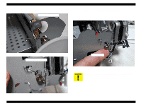
EPSON Stylus COLOR 680/777/777i 5. Open the spur gear 25.6 hook with a pair of tweezers and then slide the paper eject roller to the right while pulling it toward to remove it. Spur gear 25.6 Revision B n A D J U S T M E N T When you replace the Frame front, make sure to lubricate the R E Q U IR E D specific amount of G26 to the Frame front. Refer to the Chapter n 6 Figure6-5. When you replace the Paper eject roller with new one, make sure to lubricate the specific amount of G26 to the Spur gear 25.6. Refer to the Chapter 6 Figure. n Assemble the Paper eject roller in the following procedure. 1. Set the Spur Gear 25.6 to the cut out hole in the Main frame. 2. Align the shape with the spur gear 25.6 hole, insert the paper eject roller shaft, and then press the spur gear 25.6 hook until it is closed. 3. Slide the paper eject roller and then insert it in the shaft guide n holder. When you assemble the Front frame to the Printer mechanism, set the CR unit to the left side and assemble the Front frame n from the right side. Be careful not damage the CR lock lever. Fasten the Front frame with C.B.S Screw 3x6 F/Zn in the order of 1,2. Paper eject roller Disassembly and Assembly 2 1 n Tightening torque for screw • C.B.S 3x6 F/Zn screw for Front frame : 9+/-1 kgf.cm Disassembly 88
-
 1
1 -
2
-
3
-
4
-
5
-
6
-
7
-
8
-
9
-
10
-
11
-
12
-
13
-
14
-
15
-
16
-
17
-
18
-
19
-
20
-
21
-
22
-
23
-
24
-
25
-
26
-
27
-
28
-
29
-
30
-
31
-
32
-
33
-
34
-
35
-
36
-
37
-
38
-
39
-
40
-
41
-
42
-
43
-
44
-
45
-
46
-
47
-
48
-
49
-
50
-
51
-
52
-
53
-
54
-
55
-
56
-
57
-
58
-
59
-
60
-
61
-
62
-
63
-
64
-
65
-
66
-
67
-
68
-
69
-
70
-
71
-
72
-
73
-
74
-
75
-
76
-
77
-
78
-
79
-
80
-
81
-
82
-
 83
83 -
 84
84 -
 85
85 -
 86
86 -
 87
87 -
 88
88 -
 89
89 -
 90
90 -
 91
91 -
 92
92 -
 93
93 -
94
-
95
-
96
-
97
-
98
-
99
-
100
-
101
-
102
-
103
-
104
-
105
-
106
-
107
-
108
-
109
-
110
-
111
-
112
-
113
-
114
-
115
-
116
-
117
-
118
-
119
-
120
-
121
-
122
-
123
-
124
-
125
-
126
-
127
-
128
-
129
-
130
-
131
-
132
-
133
-
134
-
135
-
136
-
137
-
138
-
139
-
140
-
141
-
142
-
143
-
144
-
145
 |
 |