Epson 680Pro Service Manual - Page 45
Printhead Driver Circuit
 |
UPC - 010343832138
View all Epson 680Pro manuals
Add to My Manuals
Save this manual to your list of manuals |
Page 45 highlights
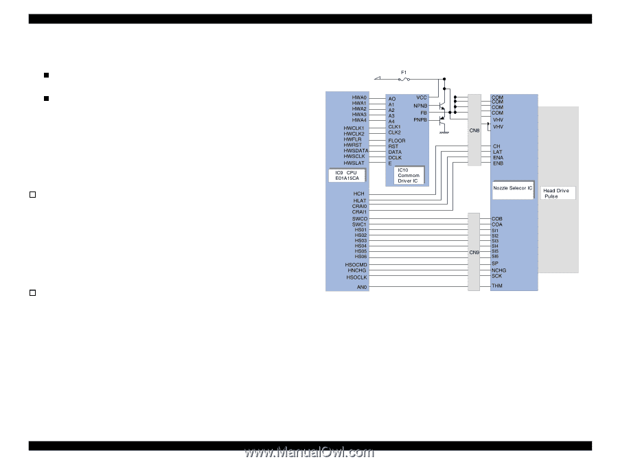
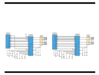
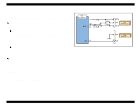
EPSON Stylus COLOR 680/777/77i 2.2.2.2 Printhead Driver Circuit The printhead driver circuit consists of the following two components: n Common driver IC (IC10:E09A14RA) directly attached to the C383MAIN board. n Nozzle selector IC on the head board. The common driver (IC10:E09A14RA) generates a reference drive waveform according to the output signals from the C383MAIN board. The reference drive waveform is amplified by the transistors Q2 and Q3and then transferred to the nozzle selector IC on the head board. Print data is converted to serial data by the CPU (IC9) and then sent to the nozzle selector IC on the head board. Based on the serial data, the nozzle selector IC determines the nozzles to be actuated. The selected nozzles are driven by the drive waveforms produced by the common driver. See Figure 2-18 for the printhead driver circuit block diagram. o Head common driver circuit The reference head drive waveform is produced in the common driver (IC10:E09A14RA) based on the following 12 signal lines output from the ASIC (IC8 E05B70CD); A0-A4, CLK1, CLK2, RST, FLOOR, DATA, DCLK, and E. By the DATA signal output from the CPU (IC9), the original data for the head drive waveform is written in the memory in the IC10. The addresses for the written data are determined by the A0 - A4 signals, and, of among, data used to determine the waveform angles is selected. Then, setting the selected data, producing trapezoid waveform value, and canceling the data are performed by the rising edges of the CLK1 and CLK2 signals. o Head nozzle selector circuit Printing data is converted into serial data by the CPU (IC9). Then the converted data is allocated to the six rows, the number of the head nozzle rows, to be transferred to the nozzle selector through the six signal lines (HS01 to HS06). Data transmission from the CPU (IC9) to the nozzle selector synchronizes with the LAT signal and SCK clock signal. Referring to the transferred data, nozzles to be activated are selected, and the PZTs of the selected nozzles are driven by the drive waveform output from the head common driver. Revision B Figure 2-18. Printhead Driver Circuit Operating Principles Electrical Circuit Operating Principles 45
-
 1
1 -
2
-
3
-
4
-
5
-
6
-
7
-
8
-
9
-
10
-
11
-
12
-
13
-
14
-
15
-
16
-
17
-
18
-
19
-
20
-
21
-
22
-
23
-
24
-
25
-
26
-
27
-
28
-
29
-
30
-
31
-
32
-
33
-
34
-
35
-
36
-
37
-
38
-
39
-
 40
40 -
 41
41 -
 42
42 -
 43
43 -
 44
44 -
 45
45 -
 46
46 -
 47
47 -
 48
48 -
 49
49 -
 50
50 -
51
-
52
-
53
-
54
-
55
-
56
-
57
-
58
-
59
-
60
-
61
-
62
-
63
-
64
-
65
-
66
-
67
-
68
-
69
-
70
-
71
-
72
-
73
-
74
-
75
-
76
-
77
-
78
-
79
-
80
-
81
-
82
-
83
-
84
-
85
-
86
-
87
-
88
-
89
-
90
-
91
-
92
-
93
-
94
-
95
-
96
-
97
-
98
-
99
-
100
-
101
-
102
-
103
-
104
-
105
-
106
-
107
-
108
-
109
-
110
-
111
-
112
-
113
-
114
-
115
-
116
-
117
-
118
-
119
-
120
-
121
-
122
-
123
-
124
-
125
-
126
-
127
-
128
-
129
-
130
-
131
-
132
-
133
-
134
-
135
-
136
-
137
-
138
-
139
-
140
-
141
-
142
-
143
-
144
-
145
 |
 |