Epson 680Pro Service Manual - Page 76
C.B.O 4x5 F/ZG for 120V Green circled screw
 |
UPC - 010343832138
View all Epson 680Pro manuals
Add to My Manuals
Save this manual to your list of manuals |
Page 76 highlights
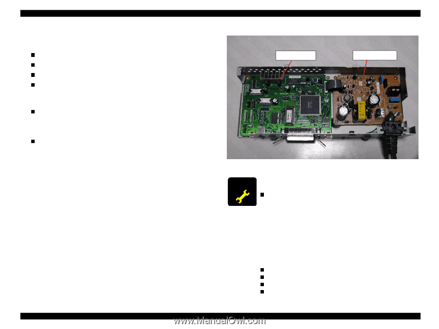
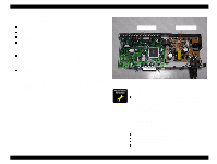
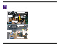
EPSON Stylus COLOR 680/777/777i Revision B 4. Holding the Left housing lightly, pull down the Circuit board unit. Then disconnect the following four cables from the corresponding connectors on the Main board. n CR motor connector cable : CN12 n PF motor connector cable : CN7 n Printhead FFC : CN8, CN9 n HP/PE sensor cable : CN4 5. Remove the following screws securing each circuit board to the Shield plate. Figure Figure 4-17. n C383 MAIN : Remove five screws. C.B.S 3x6 F/Zn (Red circled screws) : 3pcs (for Main board) C.P. 3x6 F/Zn (Yellow circled screws) : 2pcs (for Parallel I/F) connector) n C383PSB/E : Remove five screws. C.B.S 3x6 F/Zn (Yellow circled screws) : 3pcs (for PS board) C.B.S-TITE R 3x6 F/UC (Red circled screw) : 1pcs (for PS board) C.B.(O) 4x5 F/ZG for 120V (Green circled screw) :1pcs (for Earth terminal) Hexagon nut, Normal M4(Green circled) : 1pcs (for Earth terminal) (C.B.S 3x6 F/Zn for 220V (Green circled screw) : 1pcs (for Earth terminal)) NOTE: 110V type of the PS board dose not have earth wire. C383 MAIN Board C383 PSE/PSE board Figure 4-17. Remove the screw securing each circuit board A D JU S TM E N T R E Q U IR E D When replacing the Main board with a new one, perform the nfollowing service items. Before removing the Main board, connect the parallel I/F or USB Cable and try to read out the following data by using the Adjustment program. If this operation succeeds, replace the Main board and write the read out data to the new Main board through the Adjustment program. 1) I/C Ink consumption counter. 2) Waste ink drain pad counter. 3) Printhead ID input. 4) Gap adjustment (Bi-d adjustment) In case the above mentioned data are not able to be read out from the defective Main board, perform the following service items. n Replace the both ink cartridges with a brand new one. n Replace the Waste ink drain pad with a new one. n Input the Printhead ID. n Adjust the Bi-d alignment. Disassembly and Assembly Disassembly 76
-
 1
1 -
2
-
3
-
4
-
5
-
6
-
7
-
8
-
9
-
10
-
11
-
12
-
13
-
14
-
15
-
16
-
17
-
18
-
19
-
20
-
21
-
22
-
23
-
24
-
25
-
26
-
27
-
28
-
29
-
30
-
31
-
32
-
33
-
34
-
35
-
36
-
37
-
38
-
39
-
40
-
41
-
42
-
43
-
44
-
45
-
46
-
47
-
48
-
49
-
50
-
51
-
52
-
53
-
54
-
55
-
56
-
57
-
58
-
59
-
60
-
61
-
62
-
63
-
64
-
65
-
66
-
67
-
68
-
69
-
70
-
 71
71 -
 72
72 -
 73
73 -
 74
74 -
 75
75 -
 76
76 -
 77
77 -
 78
78 -
 79
79 -
 80
80 -
 81
81 -
82
-
83
-
84
-
85
-
86
-
87
-
88
-
89
-
90
-
91
-
92
-
93
-
94
-
95
-
96
-
97
-
98
-
99
-
100
-
101
-
102
-
103
-
104
-
105
-
106
-
107
-
108
-
109
-
110
-
111
-
112
-
113
-
114
-
115
-
116
-
117
-
118
-
119
-
120
-
121
-
122
-
123
-
124
-
125
-
126
-
127
-
128
-
129
-
130
-
131
-
132
-
133
-
134
-
135
-
136
-
137
-
138
-
139
-
140
-
141
-
142
-
143
-
144
-
145
 |
 |