Epson 680Pro Service Manual - Page 31
Printhead, EPSON Stylus COLOR 680/777/77i, Revision B, Operating Principles, Overview
 |
UPC - 010343832138
View all Epson 680Pro manuals
Add to My Manuals
Save this manual to your list of manuals |
Page 31 highlights
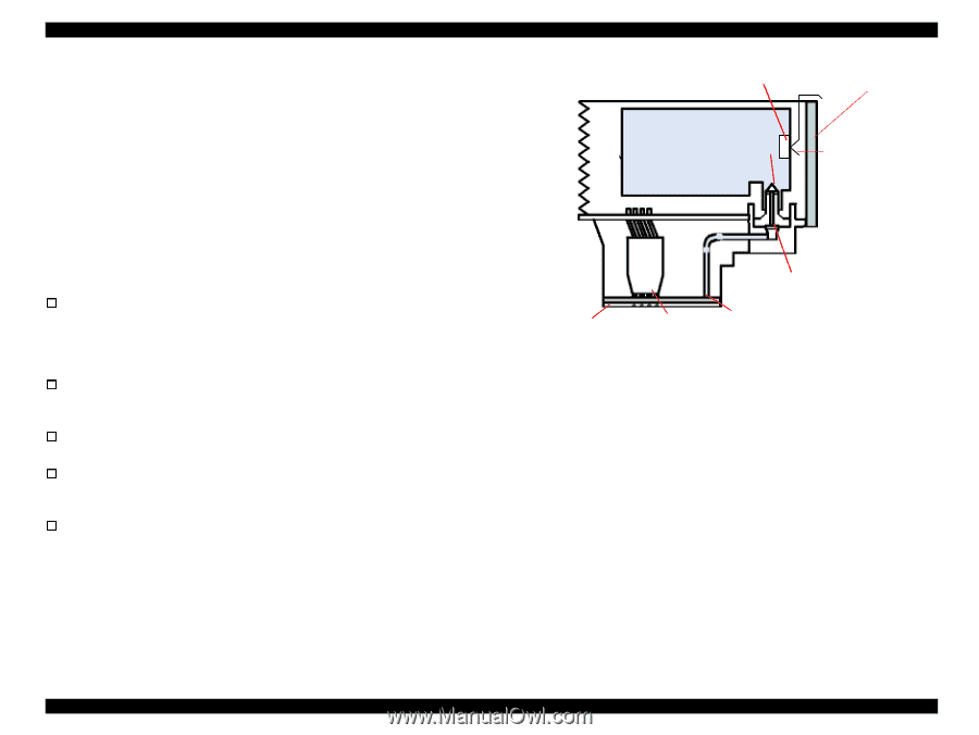
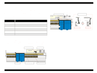
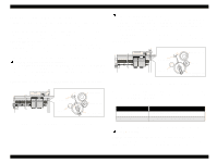
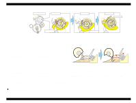
EPSON Stylus COLOR 680/777/77i 2.1.2 Printhead The printhead uses a new developed U-CHIPS head and Stylus COLOR 680/777/777i can perform multiple shot printing and variable printing. The CSIC is mounted on the ink cartridge. By storing ink life data, this IC makes it possible to control the ink in ink cartridge unit. The basic operating principles of the printhead, which plays a major role in printing, are the same as previous models; on-demand method which uses PZT (Piezo Electric Element). In order to uniform the amount of ejecting ink, the printhead has its own head ID (6 digits for this printhead) which adjust PZT voltage drive features. The printhead stores the head ID to EEPROM and generates appropriate PZT drive voltage to prevent amount of ink from varying by printheads. Following explains printhead basic components. o PZT PZT is an abbreviation of Piezo Electric Element. Certain amount of voltage expands and contracts PTZ. The drive wave generated on MAIN board drives PZT and PZT pushes the top cavity which has ink stored to discharge the ink from each nozzle on the nozzle plate. o Ink Cavity The ink absorbed from the ink cartridge goes through the filter and then is stored temporarily in this tank called "cavity" until PZT is driven. o Nozzle Plate The board with nozzle holes on the printhead surface is called Nozzle Plate. o CSIC Connection Circuit This circuit connects the CSIC mounted on the ink cartridge and the main board. One end of the wire harness connects with the print head cable to the main board. o Filter When the ink cartridge is installed, if any dirt or dust around the cartridge needle is absorbed into the head, there is a great possibility of causing nozzle clog and disturbance of ink flow, and finally causing alignment failure and dot missing. To prevent this problem, a filter is set below the cartridge needle, where ink is filtered. CSIC Revision B Nozzle Selector Board Ink Cartridge Needle CSIC Connection Circuit Filter Nozzle Plate PZT Cavity Figure 2-2. Printhead Sectional Drawing Operating Principles Overview 31
-
 1
1 -
2
-
3
-
4
-
5
-
6
-
7
-
8
-
9
-
10
-
11
-
12
-
13
-
14
-
15
-
16
-
17
-
18
-
19
-
20
-
21
-
22
-
23
-
24
-
25
-
 26
26 -
 27
27 -
 28
28 -
 29
29 -
 30
30 -
 31
31 -
 32
32 -
 33
33 -
 34
34 -
 35
35 -
 36
36 -
37
-
38
-
39
-
40
-
41
-
42
-
43
-
44
-
45
-
46
-
47
-
48
-
49
-
50
-
51
-
52
-
53
-
54
-
55
-
56
-
57
-
58
-
59
-
60
-
61
-
62
-
63
-
64
-
65
-
66
-
67
-
68
-
69
-
70
-
71
-
72
-
73
-
74
-
75
-
76
-
77
-
78
-
79
-
80
-
81
-
82
-
83
-
84
-
85
-
86
-
87
-
88
-
89
-
90
-
91
-
92
-
93
-
94
-
95
-
96
-
97
-
98
-
99
-
100
-
101
-
102
-
103
-
104
-
105
-
106
-
107
-
108
-
109
-
110
-
111
-
112
-
113
-
114
-
115
-
116
-
117
-
118
-
119
-
120
-
121
-
122
-
123
-
124
-
125
-
126
-
127
-
128
-
129
-
130
-
131
-
132
-
133
-
134
-
135
-
136
-
137
-
138
-
139
-
140
-
141
-
142
-
143
-
144
-
145
 |
 |