Epson 680Pro Service Manual - Page 96
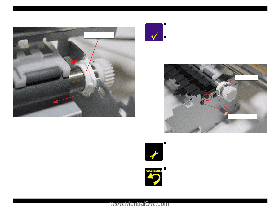
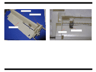
Fit the protrusions of the Left PF roller bushing to each, notches
 |
UPC - 010343832138
View all Epson 680Pro manuals
Add to My Manuals
Save this manual to your list of manuals |
Page 96 highlights
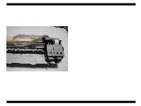
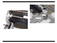
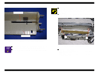
EPSON Stylus COLOR 680/777/777i 9. Fit the protrusions of the Right PF roller bushing to the notches in the frames as shown in the following figure. Right PF roller bushing Revision B CHECK P O IN T n After assemble the PF roller, make sure that the dowel of the both left and right PF roller bushing holder fit in the cut hole of n both frames. After assemble the Front paper guide to the printer mechanism, make sure that the hooks and the dowel pins on the Front paper guide is set to the fitting positions secure. Slide the Front paper guide to the right side by pushing it and make sure that the right hook on the Front paper guide is locked to the frame securely. If the Front paper guide is not fixed securely to the suitable position, it may cause the paper jam problem. Right hook Figure 4-53. Fit the protrusions of the Left PF roller bushing to each notches 10. Slide the PF roller to the left side along with the both PF roller bushings and remove the PF roller from the printer mechanism. Two dowel pins Figure 4-54. Front paper guide assembling notice n A D J U S T M E N T When you replace the PF roller with new one, be sure to R E Q U IR E D lubricate a specific amount of G-26 between the Left PF roller bushing holder and the left edge of the PF roller. Refer to Chapter 6 Figure. n When you assemble the Front frame to the Printer mechanism, set the CR unit to the left side and assemble the Front frame from the right side. Be careful not damage the CR lock lever. Disassembly and Assembly Disassembly 96
-
 1
1 -
2
-
3
-
4
-
5
-
6
-
7
-
8
-
9
-
10
-
11
-
12
-
13
-
14
-
15
-
16
-
17
-
18
-
19
-
20
-
21
-
22
-
23
-
24
-
25
-
26
-
27
-
28
-
29
-
30
-
31
-
32
-
33
-
34
-
35
-
36
-
37
-
38
-
39
-
40
-
41
-
42
-
43
-
44
-
45
-
46
-
47
-
48
-
49
-
50
-
51
-
52
-
53
-
54
-
55
-
56
-
57
-
58
-
59
-
60
-
61
-
62
-
63
-
64
-
65
-
66
-
67
-
68
-
69
-
70
-
71
-
72
-
73
-
74
-
75
-
76
-
77
-
78
-
79
-
80
-
81
-
82
-
83
-
84
-
85
-
86
-
87
-
88
-
89
-
90
-
 91
91 -
 92
92 -
 93
93 -
 94
94 -
 95
95 -
 96
96 -
 97
97 -
 98
98 -
 99
99 -
 100
100 -
 101
101 -
102
-
103
-
104
-
105
-
106
-
107
-
108
-
109
-
110
-
111
-
112
-
113
-
114
-
115
-
116
-
117
-
118
-
119
-
120
-
121
-
122
-
123
-
124
-
125
-
126
-
127
-
128
-
129
-
130
-
131
-
132
-
133
-
134
-
135
-
136
-
137
-
138
-
139
-
140
-
141
-
142
-
143
-
144
-
145
 |
 |