Epson 680Pro Service Manual - Page 124
Connector Summary, 7.1.1 Major Component Unit
 |
UPC - 010343832138
View all Epson 680Pro manuals
Add to My Manuals
Save this manual to your list of manuals |
Page 124 highlights
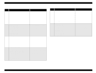
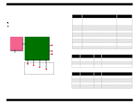
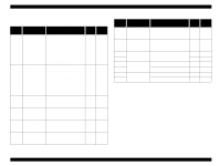
EPSON Stylus COLOR 680/777/777i 7.1 Connector Summary 7.1.1 Major Component Unit The Major component units of this printer are as follows. o Main Board (C383MAIN) o Power Supply Board (C383PSB/PSE) The figure below shows how these components connect. C383PSB/PSE CN2 CN1 AC Power CN10 C383MAIN CN8, CN9 CN7 CN12 CN3 CN1 CN11 CN4 USB Parallel I/F C383 PNL Printhead PF Motor CR Motor Printer Mechanism HP/PE Sensor Figure 7-1. Connection of the Major Components See the following tables for the connector summary for the C383MAIN board and each connector's pin alignment. Revision B Table 7-1. Connector Summary for C383MAIN/MAIN-B Connector Function Table to refer to CN1 For connection with the parallel interface Refer to "IEEE1284.4 Protocol" on page 19 CN3 For connection with the USB Refer to "USB" on page CN4 For connection with the HP/PE sensor Table 7-2 CN7 For connection with the PF motor Table 7-3 CN8, CN9 For connection with the printhead Table 7-5 CN10 For connection with the power supply board Table 7-6 CN11 For connection with the C383PNL board Table 7-x CN12 For connection with the CR motor Table 7-8 Table 7-2. CN4 - HP/PE Sensor Pin Signal Name I/O Function 1 HPPE In Sensor detect signal 2 GND --- Ground 3 HPPEV --- Sensor Power Supply Table 7-3. CN7 - PF Motor Pin Signal Name I/O Function 1 PFA Out Phase drive signal (A) 2 PFB Out Phase drive signal (-A) 3 PF-A Out Phase drive signal (B) 4 PF-B Out Phase drive signal (-B) Appendix Connector Summary 124
-
 1
1 -
2
-
3
-
4
-
5
-
6
-
7
-
8
-
9
-
10
-
11
-
12
-
13
-
14
-
15
-
16
-
17
-
18
-
19
-
20
-
21
-
22
-
23
-
24
-
25
-
26
-
27
-
28
-
29
-
30
-
31
-
32
-
33
-
34
-
35
-
36
-
37
-
38
-
39
-
40
-
41
-
42
-
43
-
44
-
45
-
46
-
47
-
48
-
49
-
50
-
51
-
52
-
53
-
54
-
55
-
56
-
57
-
58
-
59
-
60
-
61
-
62
-
63
-
64
-
65
-
66
-
67
-
68
-
69
-
70
-
71
-
72
-
73
-
74
-
75
-
76
-
77
-
78
-
79
-
80
-
81
-
82
-
83
-
84
-
85
-
86
-
87
-
88
-
89
-
90
-
91
-
92
-
93
-
94
-
95
-
96
-
97
-
98
-
99
-
100
-
101
-
102
-
103
-
104
-
105
-
106
-
107
-
108
-
109
-
110
-
111
-
112
-
113
-
114
-
115
-
116
-
117
-
118
-
 119
119 -
 120
120 -
 121
121 -
 122
122 -
 123
123 -
 124
124 -
 125
125 -
 126
126 -
 127
127 -
 128
128 -
 129
129 -
130
-
131
-
132
-
133
-
134
-
135
-
136
-
137
-
138
-
139
-
140
-
141
-
142
-
143
-
144
-
145
 |
 |
