Epson 680Pro Service Manual - Page 42
C383MAIN board., When the power is turned on, Q1 repeats on/off automatically along with
 |
UPC - 010343832138
View all Epson 680Pro manuals
Add to My Manuals
Save this manual to your list of manuals |
Page 42 highlights
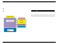
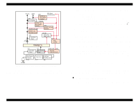
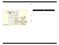
EPSON Stylus COLOR 680/777/77i o +5V line over voltage protection circuit: This protection circuit is in the same line as the +42V over voltage protection circuit is located. The output voltage level of the +5V line is monitored by a Zener diode. This circuit shuts down the +5V line forcefully when the voltage level exceeds +9V. o +42VDC line drop limitation circuit: This protection circuit is in the same line as +42V over voltage protection circuit is located. The output voltage level of the +42V line is monitored by a Zener diode. This circuit shuts down the +42V line forcefully when the voltage level drops to +36V. o +42VDC line over voltage circuit: This circuit is in the same line as +5V line over voltage protection circuit is located. The output level is monitored by two Zener diodes. If the voltage level exceeds +48VDC, this circuit shuts down the +42V line forcefully. o +5V line constant voltage/constant current control circuit: The output current is monitored by the +5VDC generation switching control IC (IC51), which also monitors the output voltage. This information is input to the internal comparator and stabilizes +5V line. The operations of the secondary side switch are explained below. n When the power is turned on, Q1 repeats on/off automatically along with the increase and decrease of energy on the trans coil at the primary side. While the power is on, the PSC signal is input to the power supply board from the C383MAIN board. n This signal turns Q84 on and it becomes possible to discharge energy between the terminals 8 and 9 of T1. At this time, even if the power is turned off, the electrolytic capacitor keeps Q84 on for a while, and by this electrolytic capacitor, voltage output is held at least 30 seconds. This time helps the printer to complete a power-off operation. Operating Principles Electrical Circuit Operating Principles Revision B 42
-
 1
1 -
2
-
3
-
4
-
5
-
6
-
7
-
8
-
9
-
10
-
11
-
12
-
13
-
14
-
15
-
16
-
17
-
18
-
19
-
20
-
21
-
22
-
23
-
24
-
25
-
26
-
27
-
28
-
29
-
30
-
31
-
32
-
33
-
34
-
35
-
36
-
 37
37 -
 38
38 -
 39
39 -
 40
40 -
 41
41 -
 42
42 -
 43
43 -
 44
44 -
 45
45 -
 46
46 -
 47
47 -
48
-
49
-
50
-
51
-
52
-
53
-
54
-
55
-
56
-
57
-
58
-
59
-
60
-
61
-
62
-
63
-
64
-
65
-
66
-
67
-
68
-
69
-
70
-
71
-
72
-
73
-
74
-
75
-
76
-
77
-
78
-
79
-
80
-
81
-
82
-
83
-
84
-
85
-
86
-
87
-
88
-
89
-
90
-
91
-
92
-
93
-
94
-
95
-
96
-
97
-
98
-
99
-
100
-
101
-
102
-
103
-
104
-
105
-
106
-
107
-
108
-
109
-
110
-
111
-
112
-
113
-
114
-
115
-
116
-
117
-
118
-
119
-
120
-
121
-
122
-
123
-
124
-
125
-
126
-
127
-
128
-
129
-
130
-
131
-
132
-
133
-
134
-
135
-
136
-
137
-
138
-
139
-
140
-
141
-
142
-
143
-
144
-
145
 |
 |