Epson 680Pro Service Manual - Page 103
Adjustment Program Installation Procedure, 5.1.4 Adjustment Program Initial Setting menu, 5.1.
 |
UPC - 010343832138
View all Epson 680Pro manuals
Add to My Manuals
Save this manual to your list of manuals |
Page 103 highlights
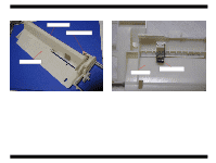
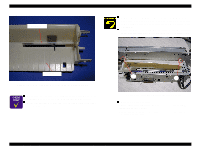
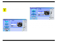
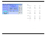
EPSON Stylus COLOR 680/777/777i Revision B 5.1.3 Adjustment Program Installation Procedure This adjustment program is in the 3.5 2HD FD. The first FD is the installer disk. When you execute Setup.exe, the installation of the program will be started under Windows 98. After installation is completed, the Stylus COLOR 680/777/777i icon will be automatically made in the program menu. Go "Start" -> "Program" and click the icon to start this program. 5.1.4 Adjustment Program Initial Setting menu You have to input the following four items before entering the adjustment main menu. o Model name (Stylus COLOR 680/777/777i) For the Stylus COLOR 777I, select Model name "Stylus COLOR 777." o Interface setting (LPT1, LPT2, LPT3, EPUSB1, EPUSB2, EPUSB3) o Destination (EURO / ASIA, EAI) Follow the procedure below to input the initial settings. 1. When you run this program, the following menu appears. Select the Stylus COLOR 680 or 777/777i in the screen below. NOTE: This printer stores model name in the PROM. Therefore, even you select the model name in the screen above, model name will not stored in the EEPROM. Selecting model name in the screen above determines respective special command for each model. 2. Select the Interface port number which you connect the printer to your PC as above Figure 5-2. 3. Select the suitable destination in the Destination menu. Figure 5-2. Model Name Selection Figure 5-3. Destination Setting 5.1.5 Head ID Input This adjustment function is required when any of the following parts is replaced. o Printhead o Main board o Printer mechanism Adjustment Overview 103
-
 1
1 -
2
-
3
-
4
-
5
-
6
-
7
-
8
-
9
-
10
-
11
-
12
-
13
-
14
-
15
-
16
-
17
-
18
-
19
-
20
-
21
-
22
-
23
-
24
-
25
-
26
-
27
-
28
-
29
-
30
-
31
-
32
-
33
-
34
-
35
-
36
-
37
-
38
-
39
-
40
-
41
-
42
-
43
-
44
-
45
-
46
-
47
-
48
-
49
-
50
-
51
-
52
-
53
-
54
-
55
-
56
-
57
-
58
-
59
-
60
-
61
-
62
-
63
-
64
-
65
-
66
-
67
-
68
-
69
-
70
-
71
-
72
-
73
-
74
-
75
-
76
-
77
-
78
-
79
-
80
-
81
-
82
-
83
-
84
-
85
-
86
-
87
-
88
-
89
-
90
-
91
-
92
-
93
-
94
-
95
-
96
-
97
-
 98
98 -
 99
99 -
 100
100 -
 101
101 -
 102
102 -
 103
103 -
 104
104 -
 105
105 -
 106
106 -
 107
107 -
 108
108 -
109
-
110
-
111
-
112
-
113
-
114
-
115
-
116
-
117
-
118
-
119
-
120
-
121
-
122
-
123
-
124
-
125
-
126
-
127
-
128
-
129
-
130
-
131
-
132
-
133
-
134
-
135
-
136
-
137
-
138
-
139
-
140
-
141
-
142
-
143
-
144
-
145
 |
 |
