Epson 680Pro Service Manual - Page 35
Paper Loading Mechanism (ASF Unit
 |
UPC - 010343832138
View all Epson 680Pro manuals
Add to My Manuals
Save this manual to your list of manuals |
Page 35 highlights
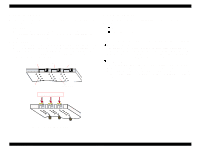
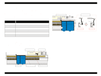
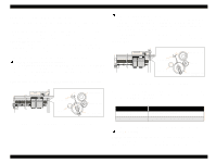
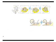
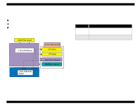
EPSON Stylus COLOR 680/777/77i 2.1.5 Paper Loading Mechanism (ASF Unit) The Paper loading mechanism is positioned at the printer rear. The Paper loading mechanism loads paper at the ASF unit and feeds paper to the PF roller. This ASF unit was designed newly for this product and consists of LD roller, Pad holder (Paper return plate), ASF Frame, Hopper, and so on. For the major feature of this ASF unit, ASF HP sensor is not used and the single LD roller is built in the ASF unit. Drive sent from the PF motor is always transmitted to the ASF unit side. But, the Change lever and the Clutch mechanism switch ON/OFF the PF motor drive to the LD roller with the motor rotational direction. Drive from the PF motor is transmitted to the ASF unit as described below: o Switch the PF motor drive to ASF unit side PF Motor pinion gear rotates CCW direction with a specific steps → Combination Gear 16, 21.6 (CW) → Spur Gear 73.6(CCW) → Spur Gear 15(CW) → Combination Gear 37.6, 44.4 (CCW) → Change Lever rotates (CCW) → Release the Clutch mechanism lock position Following Figure 2-7 shows you the switching path for PF motor drive to ASF unit side. Spur Gear 35.2 Change Lever Spur Gear 23.2 Spur Gear 15 Combination Gear 37.6, 44.4 Figure 2-7. Switch the PF motor drive to ASF unit side Revision B o Transfer the PF motor drive to LD roller PF Motor pinion gear rotates CW direction→ Combination Gear 16, 21.6 (CCW) → Spur Gear 73.6 (CW) → Spur Gear 15 (CCW) → Combination Gear 37.6, 44.4 (CW) → Change Lever rotates (CW) → Spur Gear 23.2 (CCW) → Spur Gear 35.2 (CW) (include the clutch mechanism) → LD roller (CW). Following Figure 2-9 shows the PF motor drive transmission path to the LD roller unit built in the ASF unit. The LD roller is assembled on the same shaft that the Spur gear 35.2 is assembled. Change Lever Spur Gear 35.2 Spur Gear 23.2 Spur Gear 15 Combination Gear 37.6, 44.4 Figure 2-8. PF motor drive transmission path When the PF motor torque is switched to the ASF unit side by the clutch mechanism, the function of the ASF mechanism varies depending on the rotational direction of the PF motor, as shown in the table below. Table 2-3. ASF unit function & PF Motor rotational direction Directions Clockwise (*1) Corresponding Functions • Picks up and loads paper Counterclockwise (*1) • Release the DE lever & Clutch mechanism (*1): The PF Motor rotational direction = seen from the right side of the printer. o Clutch Mechanism Unlike the previous products, this product dose not have a ASF HP sensor. Instead of the ASF HP sensor, Change lever and the Clutch mechanism are used to detect the ASF home position. Following figures describe the mechanism. Operating Principles Overview 35
-
 1
1 -
2
-
3
-
4
-
5
-
6
-
7
-
8
-
9
-
10
-
11
-
12
-
13
-
14
-
15
-
16
-
17
-
18
-
19
-
20
-
21
-
22
-
23
-
24
-
25
-
26
-
27
-
28
-
29
-
 30
30 -
 31
31 -
 32
32 -
 33
33 -
 34
34 -
 35
35 -
 36
36 -
 37
37 -
 38
38 -
 39
39 -
 40
40 -
41
-
42
-
43
-
44
-
45
-
46
-
47
-
48
-
49
-
50
-
51
-
52
-
53
-
54
-
55
-
56
-
57
-
58
-
59
-
60
-
61
-
62
-
63
-
64
-
65
-
66
-
67
-
68
-
69
-
70
-
71
-
72
-
73
-
74
-
75
-
76
-
77
-
78
-
79
-
80
-
81
-
82
-
83
-
84
-
85
-
86
-
87
-
88
-
89
-
90
-
91
-
92
-
93
-
94
-
95
-
96
-
97
-
98
-
99
-
100
-
101
-
102
-
103
-
104
-
105
-
106
-
107
-
108
-
109
-
110
-
111
-
112
-
113
-
114
-
115
-
116
-
117
-
118
-
119
-
120
-
121
-
122
-
123
-
124
-
125
-
126
-
127
-
128
-
129
-
130
-
131
-
132
-
133
-
134
-
135
-
136
-
137
-
138
-
139
-
140
-
141
-
142
-
143
-
144
-
145
 |
 |
