Epson 680Pro Service Manual - Page 46
PF Motor (PF/ PUMP/ ASF Motor) Driver Circuit, 2.2.2.4 CR Motor Driver Circuit
 |
UPC - 010343832138
View all Epson 680Pro manuals
Add to My Manuals
Save this manual to your list of manuals |
Page 46 highlights
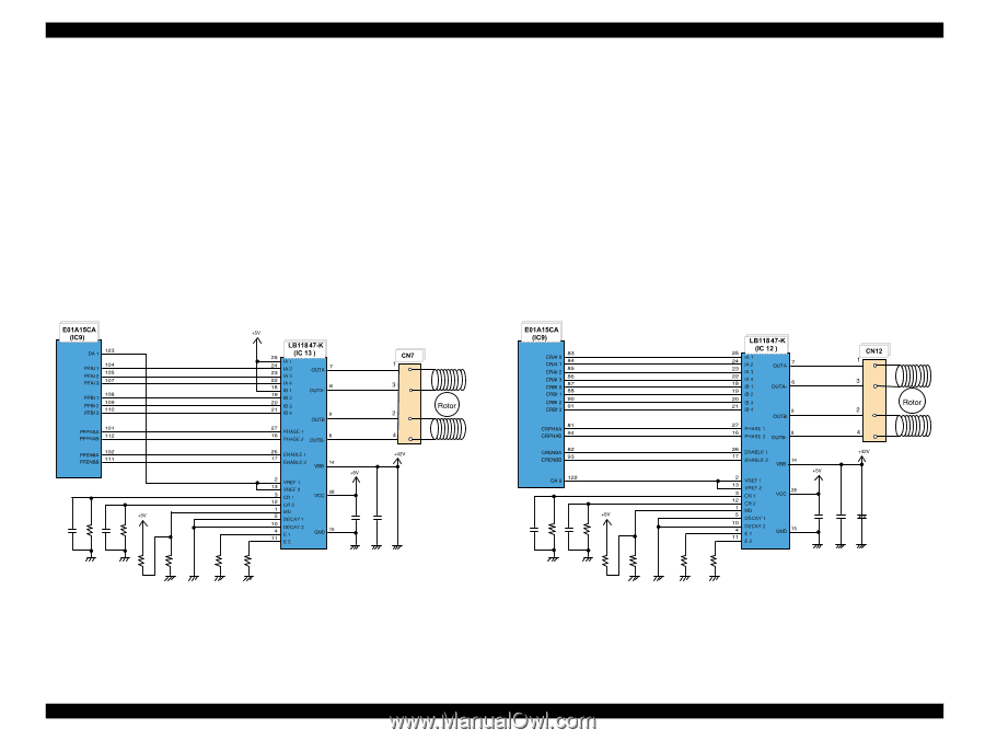
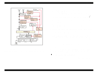
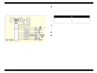
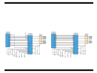
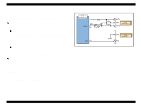
EPSON Stylus COLOR 680/777/77i Revision B 2.2.2.3 PF Motor (PF/ PUMP/ ASF Motor) Driver Circuit The motor driver IC (IC13) on the MAIN board drives PF motor. This product uses 4phase 200-pole hybrid type stepping motor and performs constant current bi-polar drive. CPU (IC9) converts PF motor phase control signal to LB11847 micro step drive form and outputs to motor driver IC (IC13) LB11847 from port 101, 112. Based on this signal, IC13 determines the phase mode. The current value on each phase is determined by CPU (IC9) and outputs from port 104, 105, 107, 108, 109, 110 to driver IC (IC13). Motor driver IC generates motor driver waveform based on these input signals and controls the motor. If the printer dose not receive any data from PC for 5 minutes, CPU set the motor drive current to 0 via port 104, 105, 107, 108, 109, 110 and the motor drive is turned off to save the power consumption. 2.2.2.4 CR Motor Driver Circuit The motor driver IC (IC12) on the MAIN board drives PF motor. This product uses 4phase 200-pole hybrid type stepping motor and performs constant current bi-polar drive. CPU (IC9) converts PF motor phase control signal to LB11847 micro step drive form and outputs to motor driver IC (IC12) LB11847 from port 81, 94. Based on this signal, IC12 determines the phase mode. The current value on each phase is determined by CPU (IC9) and outputs from port 83, 84, 85, 86, 87, 88, 90, 91 to driver IC (IC12). Motor driver IC generates motor driver waveform based on these input signals and controls the motor. If the printer dose not receive any data from PC for 5 minutes, CPU set the motor drive current to 0 via port 83, 84, 85, 86, 87, 88, 90, 91 and the motor drive is turned off to save the power consumption. Figure 2-19. PF Motor Driver Circuit Block Diagram Figure 2-20. CR Motor Driver Circuit Block Diagram Operating Principles Electrical Circuit Operating Principles 46
-
 1
1 -
2
-
3
-
4
-
5
-
6
-
7
-
8
-
9
-
10
-
11
-
12
-
13
-
14
-
15
-
16
-
17
-
18
-
19
-
20
-
21
-
22
-
23
-
24
-
25
-
26
-
27
-
28
-
29
-
30
-
31
-
32
-
33
-
34
-
35
-
36
-
37
-
38
-
39
-
40
-
 41
41 -
 42
42 -
 43
43 -
 44
44 -
 45
45 -
 46
46 -
 47
47 -
 48
48 -
 49
49 -
 50
50 -
 51
51 -
52
-
53
-
54
-
55
-
56
-
57
-
58
-
59
-
60
-
61
-
62
-
63
-
64
-
65
-
66
-
67
-
68
-
69
-
70
-
71
-
72
-
73
-
74
-
75
-
76
-
77
-
78
-
79
-
80
-
81
-
82
-
83
-
84
-
85
-
86
-
87
-
88
-
89
-
90
-
91
-
92
-
93
-
94
-
95
-
96
-
97
-
98
-
99
-
100
-
101
-
102
-
103
-
104
-
105
-
106
-
107
-
108
-
109
-
110
-
111
-
112
-
113
-
114
-
115
-
116
-
117
-
118
-
119
-
120
-
121
-
122
-
123
-
124
-
125
-
126
-
127
-
128
-
129
-
130
-
131
-
132
-
133
-
134
-
135
-
136
-
137
-
138
-
139
-
140
-
141
-
142
-
143
-
144
-
145
 |
 |