Epson 680Pro Service Manual - Page 48
Sensor Circuit, Sensor Circuit Diagram
 |
UPC - 010343832138
View all Epson 680Pro manuals
Add to My Manuals
Save this manual to your list of manuals |
Page 48 highlights
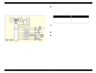
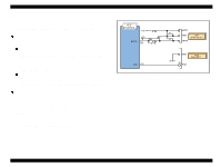
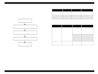
EPSON Stylus COLOR 680/777/77i 2.2.2.7 Sensor Circuit : C383 MAIN is equipped with the following two sensors to detect the status of the printer. Unlike the previous product, ASF HP sensor is not equipped on the ASF and the ASF HP is determined with the clutch mechanism (2.1.4 Paper Feeding Mechanism). o HP/PE Sensor This sensor uses photo interrupter method and detects the following three status. The photo interrupt component and two detection levers consists of this sensor. n CR home position The CR home position is detected on the right edge of the CR shaft with the HP/PE sensor during the power on sequence. In case the CR home position is detected in the power on sequence, this sensor outputs HIGH signal to the CPU. When the LOW signal is output to the CPU in the detection position, the CR unit is out of home position. n Paper Top & End position When the Paper is in the paper path, this sensor outputs the HIGH signal. When the Paper is not in the paper path, this sensor outputs the LOW signal. This status is always monitored during the printer is in the power on status with this sensor. o Thermistor (THM) The thermistor is attached directly on the printhead driver board. It monitors the temperature around the printhead and determines the proper head drive voltage according to the ink viscosity that varies by the temperature. This information is fed back to the CPU analog port. When the temperature rises, the head drive circuit lowers the drive voltage: When the temperature lowers, the head drive circuit rises the drive voltage. The block diagram for the sensor circuit is shown below Revision B 3 2 1 Figure 2-23. Sensor Circuit Diagram Operating Principles Electrical Circuit Operating Principles 48
-
 1
1 -
2
-
3
-
4
-
5
-
6
-
7
-
8
-
9
-
10
-
11
-
12
-
13
-
14
-
15
-
16
-
17
-
18
-
19
-
20
-
21
-
22
-
23
-
24
-
25
-
26
-
27
-
28
-
29
-
30
-
31
-
32
-
33
-
34
-
35
-
36
-
37
-
38
-
39
-
40
-
41
-
42
-
 43
43 -
 44
44 -
 45
45 -
 46
46 -
 47
47 -
 48
48 -
 49
49 -
 50
50 -
 51
51 -
 52
52 -
 53
53 -
54
-
55
-
56
-
57
-
58
-
59
-
60
-
61
-
62
-
63
-
64
-
65
-
66
-
67
-
68
-
69
-
70
-
71
-
72
-
73
-
74
-
75
-
76
-
77
-
78
-
79
-
80
-
81
-
82
-
83
-
84
-
85
-
86
-
87
-
88
-
89
-
90
-
91
-
92
-
93
-
94
-
95
-
96
-
97
-
98
-
99
-
100
-
101
-
102
-
103
-
104
-
105
-
106
-
107
-
108
-
109
-
110
-
111
-
112
-
113
-
114
-
115
-
116
-
117
-
118
-
119
-
120
-
121
-
122
-
123
-
124
-
125
-
126
-
127
-
128
-
129
-
130
-
131
-
132
-
133
-
134
-
135
-
136
-
137
-
138
-
139
-
140
-
141
-
142
-
143
-
144
-
145
 |
 |
