Epson 680Pro Service Manual - Page 78
Earth terminal and wire position
 |
UPC - 010343832138
View all Epson 680Pro manuals
Add to My Manuals
Save this manual to your list of manuals |
Page 78 highlights
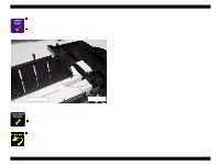
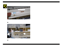
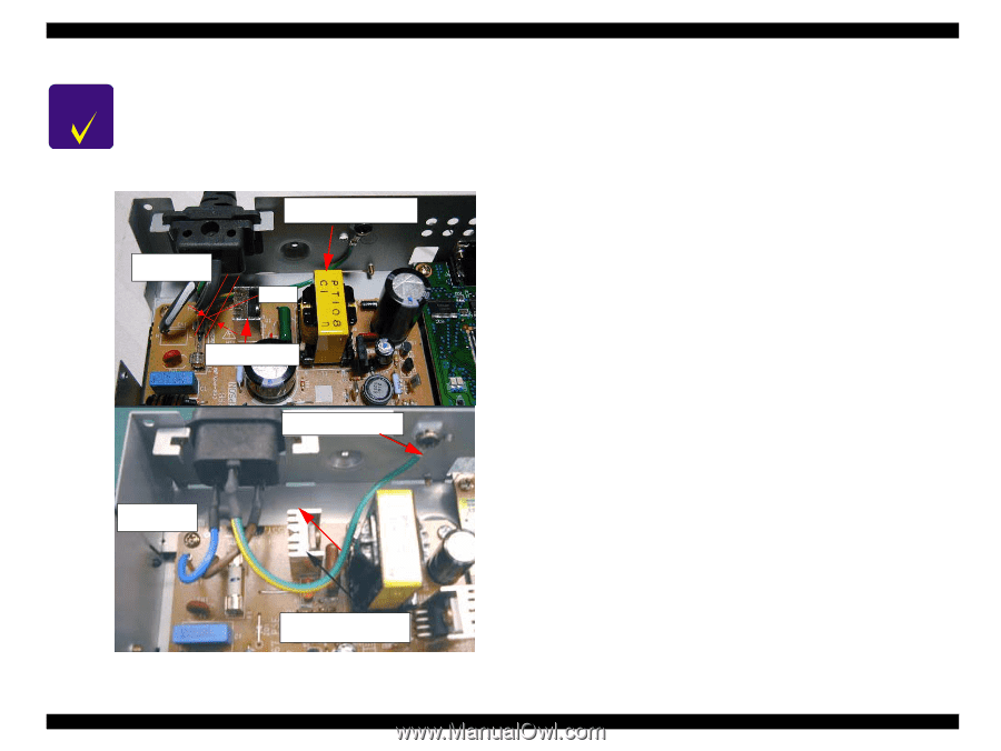
EPSON Stylus COLOR 680/777/777i CHECK P O IN T Check the Earth terminal and wire position. Refer to the following figure. The earth wire for 120V must be placed back side of the Heat sinker HT1. Be sure to leave at least 2.5 mm of space between heat sink HT1 and thewire. If this is not possible, secure the wire with tape or other methodto be sure that a minimum of 2.5 mm spacing is preserved.And the earth wire for 220V must be placed in front of the Heat sinker HT1 as following figure. Earth terminal 120V Type 2.5mm Heat sinker Earth terminal 220V Type Heat sinker Figure 4-19. Earth terminal and wire position Disassembly and Assembly Disassembly Revision B 78
-
 1
1 -
2
-
3
-
4
-
5
-
6
-
7
-
8
-
9
-
10
-
11
-
12
-
13
-
14
-
15
-
16
-
17
-
18
-
19
-
20
-
21
-
22
-
23
-
24
-
25
-
26
-
27
-
28
-
29
-
30
-
31
-
32
-
33
-
34
-
35
-
36
-
37
-
38
-
39
-
40
-
41
-
42
-
43
-
44
-
45
-
46
-
47
-
48
-
49
-
50
-
51
-
52
-
53
-
54
-
55
-
56
-
57
-
58
-
59
-
60
-
61
-
62
-
63
-
64
-
65
-
66
-
67
-
68
-
69
-
70
-
71
-
72
-
 73
73 -
 74
74 -
 75
75 -
 76
76 -
 77
77 -
 78
78 -
 79
79 -
 80
80 -
 81
81 -
 82
82 -
 83
83 -
84
-
85
-
86
-
87
-
88
-
89
-
90
-
91
-
92
-
93
-
94
-
95
-
96
-
97
-
98
-
99
-
100
-
101
-
102
-
103
-
104
-
105
-
106
-
107
-
108
-
109
-
110
-
111
-
112
-
113
-
114
-
115
-
116
-
117
-
118
-
119
-
120
-
121
-
122
-
123
-
124
-
125
-
126
-
127
-
128
-
129
-
130
-
131
-
132
-
133
-
134
-
135
-
136
-
137
-
138
-
139
-
140
-
141
-
142
-
143
-
144
-
145
 |
 |
EPSON Stylus COLOR 680/777/777i
Revision B
Disassembly and Assembly
Disassembly
78
C
H
E
C
K
P
O
I
N
T
Check the Earth terminal and wire position. Refer to the following
figure. The earth wire for 120V must be placed back side of the
Heat sinker HT1. Be sure to leave at least 2.5 mm of space between
heat sink HT1 and thewire. If this is not possible, secure the wire
with tape or other methodto be sure that a minimum of 2.5 mm
spacing is preserved.And the earth wire for 220V must be placed
in front of the Heat sinker HT1 as following figure.
Figure 4-19. Earth terminal and wire position
Earth terminal
120V Type
Heat sinker
2.5mm
Heat sinker
220V Type
Earth terminal