Epson 680Pro Service Manual - Page 47
Reset Circuit, 2.2.2.6 EEPROM Control Circuit, Reset Circuit Block Diagram
 |
UPC - 010343832138
View all Epson 680Pro manuals
Add to My Manuals
Save this manual to your list of manuals |
Page 47 highlights
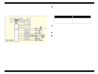
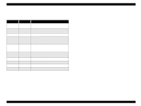
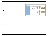
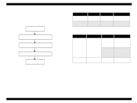
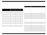
EPSON Stylus COLOR 680/777/77i 2.2.2.5 Reset Circuit Reset circuits consist of the rest IC (IC16). Reset circuits are mounted on the MAIN board to monitor the two voltages: +5V for the logic line and +42V for the drive line. When each circuit detects abnormality on the corresponding line, it outputs a reset signal to reset CPU (IC9). This function is necessary to prevent the printer from operating abnormally. This IC monitors both +5V and +45 lines but can reset them independently. The reset circuits outputs reset signal when +5V line becomes 4.2V or lower or +42V line becomes 33.2V or lower. Unlike the previous products, the timer IC is not built in the reset IC and the Lithium battery also is not equipped on the main board. . Revision B 2.2.2.6 EEPROM Control Circuit Since EEPROM is nonvolatile memory, it keeps written information if the printer power is turned off. When the printer is turned ON, CPU (IC9) reads data from EEPROM (IC15) and when the power is turned OFF it stores data to EEPROM. Information stored in EEPROM is listed below. n Various ink counter (I/C consumption counter, waste pad counter, etc.) n Mechanical setting value (Head ID, Bi-D adjustment, USB ID, etc.) See Table 7-9, "EEPROM Address Map," on page 127 that provides detailed information on the values stored in EEPROM. Figure 2-21. Reset Circuit Block Diagram Main signal lines are explained below; n OUT1: Interrupt signal n OUT2: Reset line n IN: +42V line monitoring line n VCC: +5V line monitoring line Figure 2-22. EEPROM Circuit Diagram EEPROM is connected to CPU with 4 lines and each line has the following function. n CS: Chip selection signal n CK: Data synchronism clock pulse n DI: Data writing line (serial data) at power off. n DO: Data reading line (serial data) at power on. Operating Principles Electrical Circuit Operating Principles 47
-
 1
1 -
2
-
3
-
4
-
5
-
6
-
7
-
8
-
9
-
10
-
11
-
12
-
13
-
14
-
15
-
16
-
17
-
18
-
19
-
20
-
21
-
22
-
23
-
24
-
25
-
26
-
27
-
28
-
29
-
30
-
31
-
32
-
33
-
34
-
35
-
36
-
37
-
38
-
39
-
40
-
41
-
 42
42 -
 43
43 -
 44
44 -
 45
45 -
 46
46 -
 47
47 -
 48
48 -
 49
49 -
 50
50 -
 51
51 -
 52
52 -
53
-
54
-
55
-
56
-
57
-
58
-
59
-
60
-
61
-
62
-
63
-
64
-
65
-
66
-
67
-
68
-
69
-
70
-
71
-
72
-
73
-
74
-
75
-
76
-
77
-
78
-
79
-
80
-
81
-
82
-
83
-
84
-
85
-
86
-
87
-
88
-
89
-
90
-
91
-
92
-
93
-
94
-
95
-
96
-
97
-
98
-
99
-
100
-
101
-
102
-
103
-
104
-
105
-
106
-
107
-
108
-
109
-
110
-
111
-
112
-
113
-
114
-
115
-
116
-
117
-
118
-
119
-
120
-
121
-
122
-
123
-
124
-
125
-
126
-
127
-
128
-
129
-
130
-
131
-
132
-
133
-
134
-
135
-
136
-
137
-
138
-
139
-
140
-
141
-
142
-
143
-
144
-
145
 |
 |
