HP 6125XLG R2306-HP 6125XLG Blade Switch Security Configuration Guide - Page 129
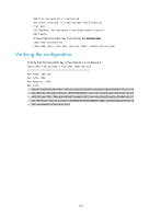
Displaying and maintaining public keys, Example for entering a peer public key, Network requirements
 |
View all HP 6125XLG manuals
Add to My Manuals
Save this manual to your list of manuals |
Page 129 highlights
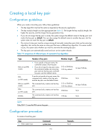
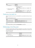
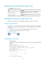
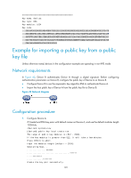
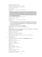
Displaying and maintaining public keys Execute display commands in any view. Task Display local public keys. Display peer public keys. Command display public-key local { dsa | ecdsa | rsa } public [ name key-name ] display public-key peer [ brief | name publickey-name ] [ name key-name ] Example for entering a peer public key Unless otherwise noted, devices in the configuration example are operating in non-FIPS mode. Network requirements As shown in Figure 39, to prevent illegal access, Device B authenticates Device A through a digital signature. Before configuring authentication parameters on Device B, configure the public key of Device A on Device B. • Configure Device B to use the asymmetric key algorithm RSA to authenticate Device A. • Manually specify the host public key of Device A on Device B. Figure 39 Network diagram Device A Device B Configuration procedure 1. Configure Device A: # Create local RSA key pairs with default names on Device A, and use the default modulus length 1024 bits. system-view [DeviceA] public-key local create rsa The range of public key modulus is (512 ~ 2048). If the key modulus is greater than 512, it will take a few minutes. Press CTRL+C to abort. Input the modulus length [default = 1024]: Generating Keys Create the key pair successfully. 120
-
 1
1 -
2
-
3
-
4
-
5
-
6
-
7
-
8
-
9
-
10
-
11
-
12
-
13
-
14
-
15
-
16
-
17
-
18
-
19
-
20
-
21
-
22
-
23
-
24
-
25
-
26
-
27
-
28
-
29
-
30
-
31
-
32
-
33
-
34
-
35
-
36
-
37
-
38
-
39
-
40
-
41
-
42
-
43
-
44
-
45
-
46
-
47
-
48
-
49
-
50
-
51
-
52
-
53
-
54
-
55
-
56
-
57
-
58
-
59
-
60
-
61
-
62
-
63
-
64
-
65
-
66
-
67
-
68
-
69
-
70
-
71
-
72
-
73
-
74
-
75
-
76
-
77
-
78
-
79
-
80
-
81
-
82
-
83
-
84
-
85
-
86
-
87
-
88
-
89
-
90
-
91
-
92
-
93
-
94
-
95
-
96
-
97
-
98
-
99
-
100
-
101
-
102
-
103
-
104
-
105
-
106
-
107
-
108
-
109
-
110
-
111
-
112
-
113
-
114
-
115
-
116
-
117
-
118
-
119
-
120
-
121
-
122
-
123
-
 124
124 -
 125
125 -
 126
126 -
 127
127 -
 128
128 -
 129
129 -
 130
130 -
 131
131 -
 132
132 -
 133
133 -
 134
134 -
135
-
136
-
137
-
138
-
139
-
140
-
141
-
142
-
143
-
144
-
145
-
146
-
147
-
148
-
149
-
150
-
151
-
152
-
153
-
154
-
155
-
156
-
157
-
158
-
159
-
160
-
161
-
162
-
163
-
164
-
165
-
166
-
167
-
168
-
169
-
170
-
171
-
172
-
173
-
174
-
175
-
176
-
177
-
178
-
179
-
180
-
181
-
182
-
183
-
184
-
185
-
186
-
187
-
188
-
189
-
190
-
191
-
192
-
193
-
194
-
195
-
196
-
197
-
198
-
199
-
200
-
201
-
202
-
203
-
204
-
205
-
206
-
207
-
208
-
209
-
210
-
211
-
212
-
213
-
214
-
215
-
216
-
217
-
218
-
219
-
220
-
221
-
222
-
223
-
224
-
225
-
226
-
227
-
228
-
229
-
230
-
231
-
232
-
233
-
234
-
235
-
236
-
237
-
238
-
239
-
240
-
241
-
242
-
243
-
244
-
245
-
246
-
247
-
248
-
249
-
250
-
251
-
252
-
253
-
254
-
255
-
256
-
257
-
258
-
259
-
260
-
261
-
262
-
263
-
264
-
265
-
266
-
267
-
268
-
269
-
270
-
271
-
272
-
273
-
274
-
275
-
276
 |
 |