HP 6125XLG R2306-HP 6125XLG Blade Switch Security Configuration Guide - Page 178
Dynamic IPv4 source guard using DHCP relay configuration example, Network requirements,
 |
View all HP 6125XLG manuals
Add to My Manuals
Save this manual to your list of manuals |
Page 178 highlights
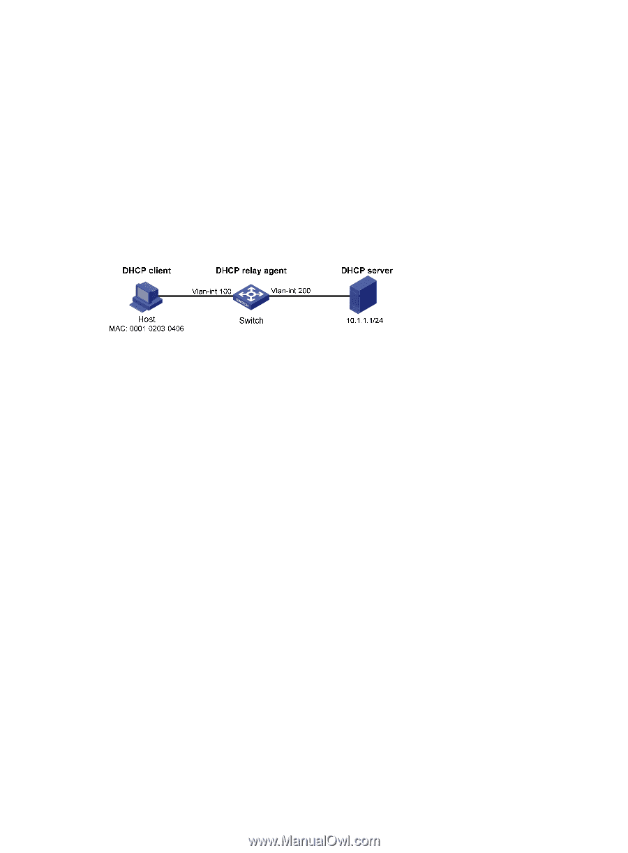
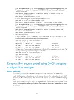
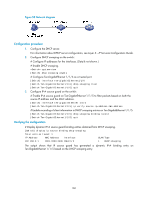
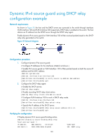
Dynamic IPv4 source guard using DHCP relay configuration example Network requirements As shown in Figure 59, the host and the DHCP server are connected to the switch through interfaces VLAN-interface 100 and VLAN-interface 200 respectively. DHCP relay is enabled on the switch. The host obtains an IP address from the DHCP server through the DHCP relay agent. Enable dynamic IPv4 source guard on VLAN-interface 100 to filter received packets based on the DHCP relay entry generated on the switch. Figure 59 Network diagram Configuration procedure 1. Configure dynamic IPv4 source guard: # Configure IP addresses for the interfaces. (Details not shown.) # Enable IPv4 source guard on VLAN-interface 100 to filter packets based on both the source IP address and the MAC address. system-view [Switch] interface vlan-interface 100 [Switch-Vlan-interface100] ip verify source ip-address mac-address [Switch-Vlan-interface100] quit 2. Configure the DHCP relay agent: # Enable the DHCP service. [Switch] dhcp enable # Enable recording DHCP relay client entries. [Switch] dhcp relay client-information record # Configure VLAN-interface 100 to work in DHCP relay mode. [Switch] interface vlan-interface 100 [Switch-Vlan-interface100] dhcp select relay # Specify the IP address of the DHCP server. [Switch-Vlan-interface100] dhcp relay server-address 10.1.1.1 [Switch-Vlan-interface100] quit Verifying the configuration # Display dynamic IPv4 source guard binding entries. [Switch] display ip source binding dhcp-relay Total entries found: 1 IP Address MAC Address Interface 192.168.0.1 0001-0203-0406 Vlan100 VLAN Type 100 DHCP relay 169
-
 1
1 -
2
-
3
-
4
-
5
-
6
-
7
-
8
-
9
-
10
-
11
-
12
-
13
-
14
-
15
-
16
-
17
-
18
-
19
-
20
-
21
-
22
-
23
-
24
-
25
-
26
-
27
-
28
-
29
-
30
-
31
-
32
-
33
-
34
-
35
-
36
-
37
-
38
-
39
-
40
-
41
-
42
-
43
-
44
-
45
-
46
-
47
-
48
-
49
-
50
-
51
-
52
-
53
-
54
-
55
-
56
-
57
-
58
-
59
-
60
-
61
-
62
-
63
-
64
-
65
-
66
-
67
-
68
-
69
-
70
-
71
-
72
-
73
-
74
-
75
-
76
-
77
-
78
-
79
-
80
-
81
-
82
-
83
-
84
-
85
-
86
-
87
-
88
-
89
-
90
-
91
-
92
-
93
-
94
-
95
-
96
-
97
-
98
-
99
-
100
-
101
-
102
-
103
-
104
-
105
-
106
-
107
-
108
-
109
-
110
-
111
-
112
-
113
-
114
-
115
-
116
-
117
-
118
-
119
-
120
-
121
-
122
-
123
-
124
-
125
-
126
-
127
-
128
-
129
-
130
-
131
-
132
-
133
-
134
-
135
-
136
-
137
-
138
-
139
-
140
-
141
-
142
-
143
-
144
-
145
-
146
-
147
-
148
-
149
-
150
-
151
-
152
-
153
-
154
-
155
-
156
-
157
-
158
-
159
-
160
-
161
-
162
-
163
-
164
-
165
-
166
-
167
-
168
-
169
-
170
-
171
-
172
-
 173
173 -
 174
174 -
 175
175 -
 176
176 -
 177
177 -
 178
178 -
 179
179 -
 180
180 -
 181
181 -
 182
182 -
 183
183 -
184
-
185
-
186
-
187
-
188
-
189
-
190
-
191
-
192
-
193
-
194
-
195
-
196
-
197
-
198
-
199
-
200
-
201
-
202
-
203
-
204
-
205
-
206
-
207
-
208
-
209
-
210
-
211
-
212
-
213
-
214
-
215
-
216
-
217
-
218
-
219
-
220
-
221
-
222
-
223
-
224
-
225
-
226
-
227
-
228
-
229
-
230
-
231
-
232
-
233
-
234
-
235
-
236
-
237
-
238
-
239
-
240
-
241
-
242
-
243
-
244
-
245
-
246
-
247
-
248
-
249
-
250
-
251
-
252
-
253
-
254
-
255
-
256
-
257
-
258
-
259
-
260
-
261
-
262
-
263
-
264
-
265
-
266
-
267
-
268
-
269
-
270
-
271
-
272
-
273
-
274
-
275
-
276
 |
 |