HP 6125XLG R2306-HP 6125XLG Blade Switch Security Configuration Guide - Page 37
Setting RADIUS timers, address. For example, if the NAS is con d with VRRP for stateful failover - uplinks
 |
View all HP 6125XLG manuals
Add to My Manuals
Save this manual to your list of manuals |
Page 37 highlights
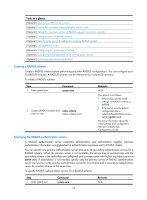
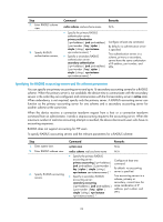
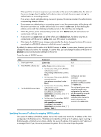
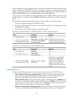
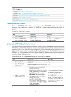
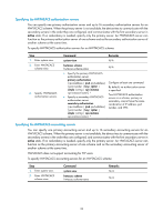
The source address of outgoing RADIUS packets is typically the IP address of an egress interface on the NAS to communicate with the RADIUS server. In some cases, however, you must change the source IP address. For example, if the NAS is configured with VRRP for stateful failover, the source IP address of outgoing RADIUS packets can be the virtual IP address of the uplink VRRP group. You can specify a source IP address for outgoing RADIUS packets in RADIUS scheme view for a specific RADIUS scheme, or in system view for all RADIUS schemes whose servers are in a VPN or the public network. Before sending a RADIUS packet, the NAS selects a source IP address in the following order: 1. The source IP address specified for the RADIUS scheme. 2. The source IP address specified in system view for the VPN or public network, depending on where the RADIUS server resides. 3. The IP address of the outbound interface specified by the route. To specify a source IP address for all RADIUS schemes in a VPN or the public network: Step Command Remarks 1. Enter system view. system-view N/A 2. Specify a source IP address radius nas-ip { ipv4-address | ipv6 By default, the IP address of the for outgoing RADIUS packets. ipv6-address } [ vpn-instance RADIUS packet outbound interface vpn-instance-name ] is used as the source IP address. To specify a source IP address for a specific RADIUS scheme: Step 1. Enter system view. 2. Enter RADIUS scheme view. Command system-view radius scheme radius-scheme-name 3. Specify a source IP address nas-ip { ipv4-address | ipv6 for outgoing RADIUS packets. ipv6-address } Remarks N/A N/A By default, the source IP address specified by the radius nas-ip command in the system view is used. If no source IP address is specified, the IP address of the RADIUS packet outbound interface is used. Setting RADIUS timers The device uses the following types of timers to control the communication with a RADIUS server: • Server response timeout timer (response-timeout)-Defines the RADIUS request retransmission interval. The timer starts immediately after a RADIUS request is sent. If the device receives no response from the RADIUS server before the timer expires, it resends the request. • Server quiet timer (quiet)-Defines the duration to keep an unreachable server in blocked state. If one server is not reachable, the device changes the server's status to blocked, starts this timer for the server, and tries to communicate with another server in active state. After the server quiet timer expires, the device changes the status of the server back to active. • Real-time accounting timer (realtime-accounting)-Defines the interval at which the device sends real-time accounting packets to the RADIUS accounting server for online users. To implement 28
-
 1
1 -
2
-
3
-
4
-
5
-
6
-
7
-
8
-
9
-
10
-
11
-
12
-
13
-
14
-
15
-
16
-
17
-
18
-
19
-
20
-
21
-
22
-
23
-
24
-
25
-
26
-
27
-
28
-
29
-
30
-
31
-
 32
32 -
 33
33 -
 34
34 -
 35
35 -
 36
36 -
 37
37 -
 38
38 -
 39
39 -
 40
40 -
 41
41 -
 42
42 -
43
-
44
-
45
-
46
-
47
-
48
-
49
-
50
-
51
-
52
-
53
-
54
-
55
-
56
-
57
-
58
-
59
-
60
-
61
-
62
-
63
-
64
-
65
-
66
-
67
-
68
-
69
-
70
-
71
-
72
-
73
-
74
-
75
-
76
-
77
-
78
-
79
-
80
-
81
-
82
-
83
-
84
-
85
-
86
-
87
-
88
-
89
-
90
-
91
-
92
-
93
-
94
-
95
-
96
-
97
-
98
-
99
-
100
-
101
-
102
-
103
-
104
-
105
-
106
-
107
-
108
-
109
-
110
-
111
-
112
-
113
-
114
-
115
-
116
-
117
-
118
-
119
-
120
-
121
-
122
-
123
-
124
-
125
-
126
-
127
-
128
-
129
-
130
-
131
-
132
-
133
-
134
-
135
-
136
-
137
-
138
-
139
-
140
-
141
-
142
-
143
-
144
-
145
-
146
-
147
-
148
-
149
-
150
-
151
-
152
-
153
-
154
-
155
-
156
-
157
-
158
-
159
-
160
-
161
-
162
-
163
-
164
-
165
-
166
-
167
-
168
-
169
-
170
-
171
-
172
-
173
-
174
-
175
-
176
-
177
-
178
-
179
-
180
-
181
-
182
-
183
-
184
-
185
-
186
-
187
-
188
-
189
-
190
-
191
-
192
-
193
-
194
-
195
-
196
-
197
-
198
-
199
-
200
-
201
-
202
-
203
-
204
-
205
-
206
-
207
-
208
-
209
-
210
-
211
-
212
-
213
-
214
-
215
-
216
-
217
-
218
-
219
-
220
-
221
-
222
-
223
-
224
-
225
-
226
-
227
-
228
-
229
-
230
-
231
-
232
-
233
-
234
-
235
-
236
-
237
-
238
-
239
-
240
-
241
-
242
-
243
-
244
-
245
-
246
-
247
-
248
-
249
-
250
-
251
-
252
-
253
-
254
-
255
-
256
-
257
-
258
-
259
-
260
-
261
-
262
-
263
-
264
-
265
-
266
-
267
-
268
-
269
-
270
-
271
-
272
-
273
-
274
-
275
-
276
 |
 |