HP ET115AV HP xw4400 Workstation - Service and Technical Reference Guide - Page 108
System board, CAUTION,
 |
View all HP ET115AV manuals
Add to My Manuals
Save this manual to your list of manuals |
Page 108 highlights
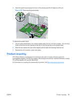
CAUTION: Avoid bending the protrusions in the CPU socket. This mishandling can damage the CPU socket. NOTE: Store the processor in a safe place where it will not be damaged. To replace the processor: 1. Disconnect power from the system (Predisassembly procedures on page 57), remove the side access panel (Side access panel on page 62), the CPU heatsink (CPU heatsink on page 95), and the processor (Processor on page 97). 2. Raise the processor socket handle fully (the full swing angle of the lever is approximately 90 degrees). CAUTION: Processor pins are delicate and bend easily. Use extreme care when placing the processor in the socket to avoid bending pins. 3. Align the triangle on the top of the processor with the triangle on the corner of the processor socket and install the processor into the socket. Ensure that the underside of the processor is level with the top of the processor socket. Lightly press down on the top of the processor while closing the socket lever. Figure 4-57 Seating the processor 4. Check for proper processor seating in the socket by carefully trying to lift the processor out of the socket with your fingers. A properly seated processor does not lift out of the socket. System board To remove the system board: 1. Disconnect power from the system (Predisassembly procedures on page 57) and remove the side access panel (Side access panel on page 62), remove all expansion boards, graphics cards, and the CPU heatsink (CPU heatsink on page 95) 2. Disconnect all cabling from the system board. NOTE: Make note of the cable connections before disconnecting them from the system board. Refer to Power connections to drives on page 82 for more information. 3. Press the release tab (1) as shown in the following illustration. 98 Chapter 4 Removal and replacement procedures ENWW
-
 1
1 -
2
-
3
-
4
-
5
-
6
-
7
-
8
-
9
-
10
-
11
-
12
-
13
-
14
-
15
-
16
-
17
-
18
-
19
-
20
-
21
-
22
-
23
-
24
-
25
-
26
-
27
-
28
-
29
-
30
-
31
-
32
-
33
-
34
-
35
-
36
-
37
-
38
-
39
-
40
-
41
-
42
-
43
-
44
-
45
-
46
-
47
-
48
-
49
-
50
-
51
-
52
-
53
-
54
-
55
-
56
-
57
-
58
-
59
-
60
-
61
-
62
-
63
-
64
-
65
-
66
-
67
-
68
-
69
-
70
-
71
-
72
-
73
-
74
-
75
-
76
-
77
-
78
-
79
-
80
-
81
-
82
-
83
-
84
-
85
-
86
-
87
-
88
-
89
-
90
-
91
-
92
-
93
-
94
-
95
-
96
-
97
-
98
-
99
-
100
-
101
-
102
-
 103
103 -
 104
104 -
 105
105 -
 106
106 -
 107
107 -
 108
108 -
 109
109 -
 110
110 -
 111
111 -
 112
112 -
 113
113 -
114
-
115
-
116
-
117
-
118
-
119
-
120
-
121
-
122
-
123
-
124
-
125
-
126
-
127
-
128
-
129
-
130
-
131
-
132
-
133
-
134
-
135
-
136
-
137
-
138
-
139
-
140
-
141
-
142
-
143
-
144
-
145
-
146
-
147
-
148
-
149
-
150
-
151
-
152
-
153
-
154
-
155
-
156
-
157
-
158
-
159
-
160
-
161
-
162
-
163
-
164
-
165
-
166
-
167
-
168
-
169
-
170
-
171
-
172
-
173
-
174
-
175
-
176
-
177
-
178
-
179
-
180
-
181
-
182
-
183
-
184
-
185
-
186
-
187
-
188
-
189
-
190
 |
 |
