HP ET115AV HP xw4400 Workstation - Service and Technical Reference Guide - Page 157
CAUTION, never
 |
View all HP ET115AV manuals
Add to My Manuals
Save this manual to your list of manuals |
Page 157 highlights
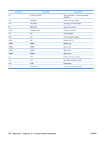
ATA/ATAPI (IDE) standard drive cable connector 14 DD13 28 CSEL 24-Pin Main power connector 13 24 1 1 2 3 4 5 6 7 12 +3.3 V +3.3 V GND +5 V GND +5 V GND 8 POK 14 -12 VL 21 +5 V GND 9 +5 Vaux 15 GND 22 +5 V and 10 +12 V-B 16 PS_O N_l +5 V-Rsense 11 +12 V-A 17 GND 23 +5 V 12 +3.3 V 18 GND 24 GND 13 +3.3 V 19 GND +3.3V-Rsense 20 GND CAUTION: Be sure you can differentiate between which power cable connects to the PCI Express x16 graphics card and which power cable connects to the system board. These two cables have different pin counts and different colors. The PCI Express power cable has a 6-pin black connector, and the system board power cable has an 8-pin white connector. When power is present, you must never connect the PCI Express power cable to the system board. If you do so, the system board may be damaged and your warranty voided. To see a picture of the PCI Express cable and where it must be connected, see PCI Express on page 75. 6-Pin power (auxiliary system board) connector 46 13 Pin Color Signal 1 BLK w/ORG +3.3V 2 BLK w/ORG +3.3V 3 YEL +12V-A 4 BLK GND 5 BLK 6 YEL GND -12V ENWW Connector pin descriptions 147
-
 1
1 -
2
-
3
-
4
-
5
-
6
-
7
-
8
-
9
-
10
-
11
-
12
-
13
-
14
-
15
-
16
-
17
-
18
-
19
-
20
-
21
-
22
-
23
-
24
-
25
-
26
-
27
-
28
-
29
-
30
-
31
-
32
-
33
-
34
-
35
-
36
-
37
-
38
-
39
-
40
-
41
-
42
-
43
-
44
-
45
-
46
-
47
-
48
-
49
-
50
-
51
-
52
-
53
-
54
-
55
-
56
-
57
-
58
-
59
-
60
-
61
-
62
-
63
-
64
-
65
-
66
-
67
-
68
-
69
-
70
-
71
-
72
-
73
-
74
-
75
-
76
-
77
-
78
-
79
-
80
-
81
-
82
-
83
-
84
-
85
-
86
-
87
-
88
-
89
-
90
-
91
-
92
-
93
-
94
-
95
-
96
-
97
-
98
-
99
-
100
-
101
-
102
-
103
-
104
-
105
-
106
-
107
-
108
-
109
-
110
-
111
-
112
-
113
-
114
-
115
-
116
-
117
-
118
-
119
-
120
-
121
-
122
-
123
-
124
-
125
-
126
-
127
-
128
-
129
-
130
-
131
-
132
-
133
-
134
-
135
-
136
-
137
-
138
-
139
-
140
-
141
-
142
-
143
-
144
-
145
-
146
-
147
-
148
-
149
-
150
-
151
-
 152
152 -
 153
153 -
 154
154 -
 155
155 -
 156
156 -
 157
157 -
 158
158 -
 159
159 -
 160
160 -
 161
161 -
 162
162 -
163
-
164
-
165
-
166
-
167
-
168
-
169
-
170
-
171
-
172
-
173
-
174
-
175
-
176
-
177
-
178
-
179
-
180
-
181
-
182
-
183
-
184
-
185
-
186
-
187
-
188
-
189
-
190
 |
 |
