HP ET115AV HP xw4400 Workstation - Service and Technical Reference Guide - Page 73
Front Bezel, Bezel blanks,
 |
View all HP ET115AV manuals
Add to My Manuals
Save this manual to your list of manuals |
Page 73 highlights
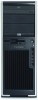
To replace the side access panel, align the bottom groove of the side access panel with the bottom edge of the chassis, rotate the side access panel toward the chassis and press firmly until the latch engages. Front Bezel 1. Lift up on the two release snaps (1) located on the front bezel. 2. Rotate the front bezel away (2) from the chassis to remove the bezel. Figure 4-7 Opening the front bezel To replace the front bezel, align front bezel on the bottom and rotate in until it snaps into place. Bezel blanks To remove the bezel blanks: 1. Disconnect power from the system (Predisassembly procedures on page 57) and remove the front bezel (Front Bezel on page 63). 2. Gently push the subpanel (1) out the back of the front bezel. 3. Remove the desired bezel blank by applying outward pressure on the subpanel (1) and pulling the blank (2) away. Figure 4-8 Removing the bezel blanks ENWW Steps for removal and replacement of components 63
-
 1
1 -
2
-
3
-
4
-
5
-
6
-
7
-
8
-
9
-
10
-
11
-
12
-
13
-
14
-
15
-
16
-
17
-
18
-
19
-
20
-
21
-
22
-
23
-
24
-
25
-
26
-
27
-
28
-
29
-
30
-
31
-
32
-
33
-
34
-
35
-
36
-
37
-
38
-
39
-
40
-
41
-
42
-
43
-
44
-
45
-
46
-
47
-
48
-
49
-
50
-
51
-
52
-
53
-
54
-
55
-
56
-
57
-
58
-
59
-
60
-
61
-
62
-
63
-
64
-
65
-
66
-
67
-
 68
68 -
 69
69 -
 70
70 -
 71
71 -
 72
72 -
 73
73 -
 74
74 -
 75
75 -
 76
76 -
 77
77 -
 78
78 -
79
-
80
-
81
-
82
-
83
-
84
-
85
-
86
-
87
-
88
-
89
-
90
-
91
-
92
-
93
-
94
-
95
-
96
-
97
-
98
-
99
-
100
-
101
-
102
-
103
-
104
-
105
-
106
-
107
-
108
-
109
-
110
-
111
-
112
-
113
-
114
-
115
-
116
-
117
-
118
-
119
-
120
-
121
-
122
-
123
-
124
-
125
-
126
-
127
-
128
-
129
-
130
-
131
-
132
-
133
-
134
-
135
-
136
-
137
-
138
-
139
-
140
-
141
-
142
-
143
-
144
-
145
-
146
-
147
-
148
-
149
-
150
-
151
-
152
-
153
-
154
-
155
-
156
-
157
-
158
-
159
-
160
-
161
-
162
-
163
-
164
-
165
-
166
-
167
-
168
-
169
-
170
-
171
-
172
-
173
-
174
-
175
-
176
-
177
-
178
-
179
-
180
-
181
-
182
-
183
-
184
-
185
-
186
-
187
-
188
-
189
-
190
 |
 |
