HP ET115AV HP xw4400 Workstation - Service and Technical Reference Guide - Page 65
Screws, Special handling of components, WARNING
 |
View all HP ET115AV manuals
Add to My Manuals
Save this manual to your list of manuals |
Page 65 highlights
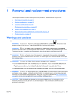
Screws The screws used in the workstation are not interchangeable. They might have standard or metric threads and might be of different lengths. If an incorrect screw is used during the reassembly process, it can damage the unit. HP strongly recommends that all screws removed during disassembly be kept with the removed part, and then returned to their proper locations. NOTE: Metric screws have a black finish. American National (unified) screws have a silver finish. NOTE: As each subassembly is removed from the workstation, place the subassembly away from the work area to prevent damage. If necessary, additional drive guide screws are provided on the system chassis. There are eight Metric screws (1) located on the chassis near the 5.25-inch optical drive bays. These screws can be used to mount additional optical drives or an optional diskette drive. There are four American National screws (2) located on the chassis near the hard drive. These screws can be used to mount additional hard drives in the 3.5" hard drive cage. NOTE: The Metric (black) and American National (silver) screws are not interchangeable. Figure 4-1 Metric and American National screw identification 1 Metric screws 2 American National screws Special handling of components The following components require special handling when servicing the workstation. WARNING! Do not use the front bezel as a handle or lifting point when lifting or moving the workstation. Lifting the workstation from the front bezel or lifting it incorrectly could cause the unit to fall and cause harm to the user and damage to the workstation. To properly and safely lift the workstation, lift it from the bottom of the unit from either the desktop or minitower configuration. ENWW Service considerations 55
-
 1
1 -
2
-
3
-
4
-
5
-
6
-
7
-
8
-
9
-
10
-
11
-
12
-
13
-
14
-
15
-
16
-
17
-
18
-
19
-
20
-
21
-
22
-
23
-
24
-
25
-
26
-
27
-
28
-
29
-
30
-
31
-
32
-
33
-
34
-
35
-
36
-
37
-
38
-
39
-
40
-
41
-
42
-
43
-
44
-
45
-
46
-
47
-
48
-
49
-
50
-
51
-
52
-
53
-
54
-
55
-
56
-
57
-
58
-
59
-
 60
60 -
 61
61 -
 62
62 -
 63
63 -
 64
64 -
 65
65 -
 66
66 -
 67
67 -
 68
68 -
 69
69 -
 70
70 -
71
-
72
-
73
-
74
-
75
-
76
-
77
-
78
-
79
-
80
-
81
-
82
-
83
-
84
-
85
-
86
-
87
-
88
-
89
-
90
-
91
-
92
-
93
-
94
-
95
-
96
-
97
-
98
-
99
-
100
-
101
-
102
-
103
-
104
-
105
-
106
-
107
-
108
-
109
-
110
-
111
-
112
-
113
-
114
-
115
-
116
-
117
-
118
-
119
-
120
-
121
-
122
-
123
-
124
-
125
-
126
-
127
-
128
-
129
-
130
-
131
-
132
-
133
-
134
-
135
-
136
-
137
-
138
-
139
-
140
-
141
-
142
-
143
-
144
-
145
-
146
-
147
-
148
-
149
-
150
-
151
-
152
-
153
-
154
-
155
-
156
-
157
-
158
-
159
-
160
-
161
-
162
-
163
-
164
-
165
-
166
-
167
-
168
-
169
-
170
-
171
-
172
-
173
-
174
-
175
-
176
-
177
-
178
-
179
-
180
-
181
-
182
-
183
-
184
-
185
-
186
-
187
-
188
-
189
-
190
 |
 |
