HP ET115AV HP xw4400 Workstation - Service and Technical Reference Guide - Page 89
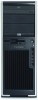
Front PCI card guide and fan removal (optional),
 |
View all HP ET115AV manuals
Add to My Manuals
Save this manual to your list of manuals |
Page 89 highlights
5. Install a PCI slot cover and close the PCI levers. If the PCI levers do not closed, be sure all cards are properly seated and then try again. Figure 4-27 Removing the IEEE-1394 To install an IEEE-1394 card, reverse the previous steps. Front PCI card guide and fan removal (optional) NOTE: The fan is only used for special configurations, but the card guide is used with all full-length add-in cards. 1. Disconnect power from the system (Predisassembly procedures on page 57), remove the side access panel (Side access panel on page 62), and remove the front bezel (Front Bezel on page 63). 2. Disconnect the fan wire (1) from the connector on the system board and thread it out of the card guide. ENWW Steps for removal and replacement of components 79
-
 1
1 -
2
-
3
-
4
-
5
-
6
-
7
-
8
-
9
-
10
-
11
-
12
-
13
-
14
-
15
-
16
-
17
-
18
-
19
-
20
-
21
-
22
-
23
-
24
-
25
-
26
-
27
-
28
-
29
-
30
-
31
-
32
-
33
-
34
-
35
-
36
-
37
-
38
-
39
-
40
-
41
-
42
-
43
-
44
-
45
-
46
-
47
-
48
-
49
-
50
-
51
-
52
-
53
-
54
-
55
-
56
-
57
-
58
-
59
-
60
-
61
-
62
-
63
-
64
-
65
-
66
-
67
-
68
-
69
-
70
-
71
-
72
-
73
-
74
-
75
-
76
-
77
-
78
-
79
-
80
-
81
-
82
-
83
-
 84
84 -
 85
85 -
 86
86 -
 87
87 -
 88
88 -
 89
89 -
 90
90 -
 91
91 -
 92
92 -
 93
93 -
 94
94 -
95
-
96
-
97
-
98
-
99
-
100
-
101
-
102
-
103
-
104
-
105
-
106
-
107
-
108
-
109
-
110
-
111
-
112
-
113
-
114
-
115
-
116
-
117
-
118
-
119
-
120
-
121
-
122
-
123
-
124
-
125
-
126
-
127
-
128
-
129
-
130
-
131
-
132
-
133
-
134
-
135
-
136
-
137
-
138
-
139
-
140
-
141
-
142
-
143
-
144
-
145
-
146
-
147
-
148
-
149
-
150
-
151
-
152
-
153
-
154
-
155
-
156
-
157
-
158
-
159
-
160
-
161
-
162
-
163
-
164
-
165
-
166
-
167
-
168
-
169
-
170
-
171
-
172
-
173
-
174
-
175
-
176
-
177
-
178
-
179
-
180
-
181
-
182
-
183
-
184
-
185
-
186
-
187
-
188
-
189
-
190
 |
 |
