HP ET115AV HP xw4400 Workstation - Service and Technical Reference Guide - Page 72
Side access panel, WARNING,
 |
View all HP ET115AV manuals
Add to My Manuals
Save this manual to your list of manuals |
Page 72 highlights
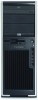
2. Remove the screw attaching the lock to the chassis. Side access panel Before accessing the internal components of the workstation, the side access panel must be removed. To remove the side access panel: WARNING! Before removing the workstation side access panel, be sure that the workstation is powered off and that the power cord is disconnected from the electrical outlet. 1. Disconnect power from the system (Predisassembly procedures on page 57) and lay the workstation on its side as shown. 2. If necessary, unlock the side access panel. The keys are on the rear panel. Also, unlock any other locks that are present (Cable lock or Padlock). 3. Pull up on the latch (1), slide the side access panel 2 toward the rear of the workstation and then lift off the cover (2). Figure 4-6 Opening the side access panel 62 Chapter 4 Removal and replacement procedures ENWW
-
 1
1 -
2
-
3
-
4
-
5
-
6
-
7
-
8
-
9
-
10
-
11
-
12
-
13
-
14
-
15
-
16
-
17
-
18
-
19
-
20
-
21
-
22
-
23
-
24
-
25
-
26
-
27
-
28
-
29
-
30
-
31
-
32
-
33
-
34
-
35
-
36
-
37
-
38
-
39
-
40
-
41
-
42
-
43
-
44
-
45
-
46
-
47
-
48
-
49
-
50
-
51
-
52
-
53
-
54
-
55
-
56
-
57
-
58
-
59
-
60
-
61
-
62
-
63
-
64
-
65
-
66
-
 67
67 -
 68
68 -
 69
69 -
 70
70 -
 71
71 -
 72
72 -
 73
73 -
 74
74 -
 75
75 -
 76
76 -
 77
77 -
78
-
79
-
80
-
81
-
82
-
83
-
84
-
85
-
86
-
87
-
88
-
89
-
90
-
91
-
92
-
93
-
94
-
95
-
96
-
97
-
98
-
99
-
100
-
101
-
102
-
103
-
104
-
105
-
106
-
107
-
108
-
109
-
110
-
111
-
112
-
113
-
114
-
115
-
116
-
117
-
118
-
119
-
120
-
121
-
122
-
123
-
124
-
125
-
126
-
127
-
128
-
129
-
130
-
131
-
132
-
133
-
134
-
135
-
136
-
137
-
138
-
139
-
140
-
141
-
142
-
143
-
144
-
145
-
146
-
147
-
148
-
149
-
150
-
151
-
152
-
153
-
154
-
155
-
156
-
157
-
158
-
159
-
160
-
161
-
162
-
163
-
164
-
165
-
166
-
167
-
168
-
169
-
170
-
171
-
172
-
173
-
174
-
175
-
176
-
177
-
178
-
179
-
180
-
181
-
182
-
183
-
184
-
185
-
186
-
187
-
188
-
189
-
190
 |
 |
