HP Vectra XU 6/XXX HP Vectra XU6/150 PC - User’s Guide - Page 97
The Pc's Memory Map
 |
View all HP Vectra XU 6/XXX manuals
Add to My Manuals
Save this manual to your list of manuals |
Page 97 highlights
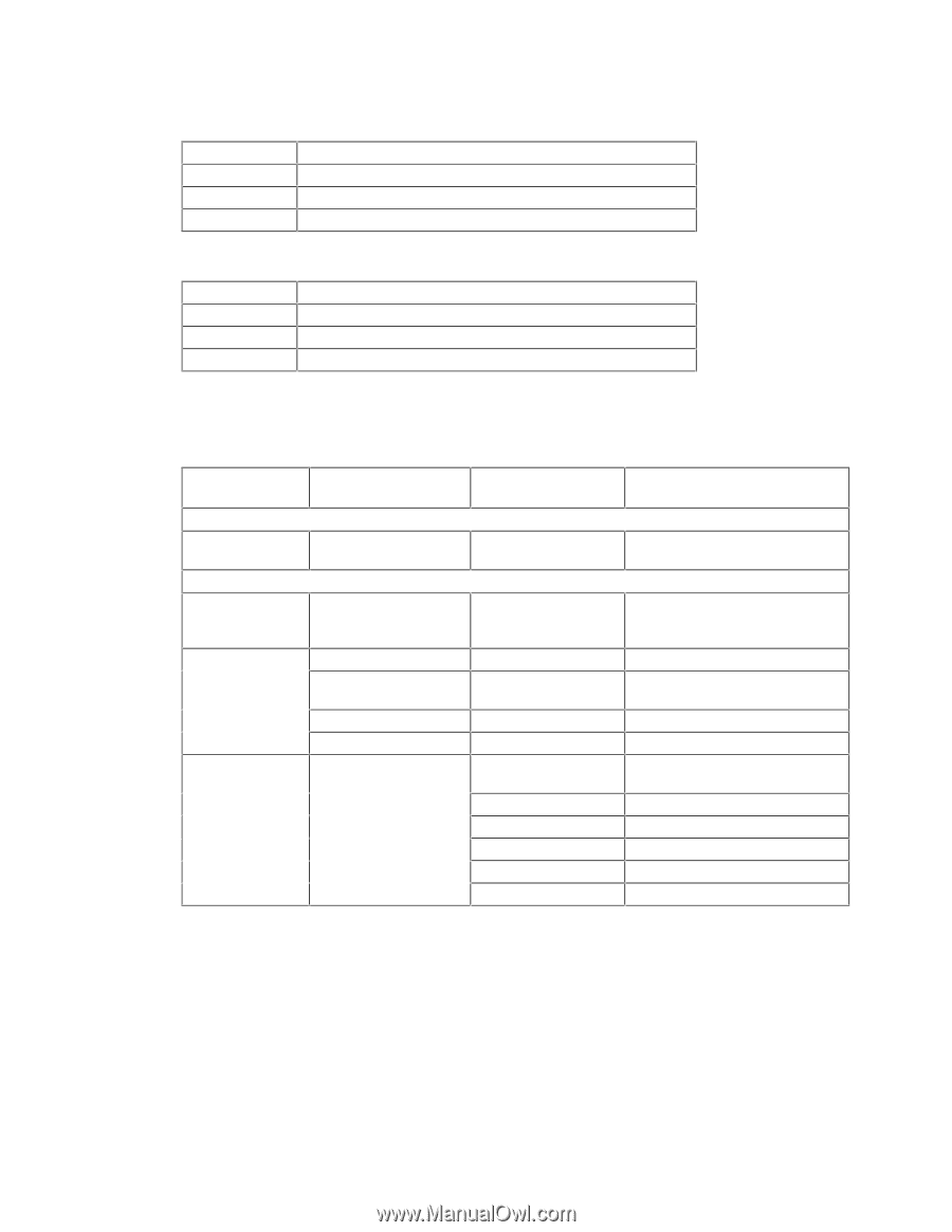
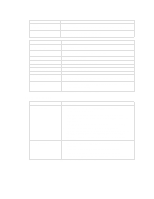
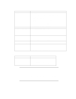
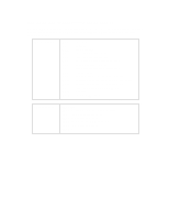
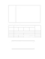
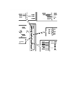
Typical Power Consumption/Availability for ISA Accessory Slots +5 V +12 V - 5 V -12 V 1 A limit per slot (limited by system board) 0.2 A limit per slot (limited by system board) 0.2 A total power limit (limited by power supply) 0.5 A total power limit (limited by power supply) Typical Power Consumption/Availability for PCI Accessory Slots +3.3 V +5 V +12 V -12 V 2.5 A maximum per slot 2.5 A maximum per slot 0.2 A maximum per slot 0.2 A maximum per slot There is a maximum per-slot limit of 15 W between all supply rails. THE PC'S MEMORY MAP Memory Area Memory Range Hexadecimal Address Range Extended Memory: 1 MB to 256 MB Extended memory 1024 KB upward 01000 to 0F0000 Conventional Memory: 0 KB to 1024 KB (1 MB) 384 KB Reserved Memory Area 960 KB to 1024 KB 0F0000 to 010000 896 KB to 960 KB 0E0000 to 0F0000 800 KB to 896 KB 0C8000 to 0E0000 640 KB Base Memory Area 768 KB to 800 KB 640 KB to 768 KB 0 KB to 640 KB 0C0000 to 0C8000 0A0000 to 0C0000 09F000 to 0A0000 - - 0500 to 0700 0400 to 04FF 0000 to 03FF Used By Windows Applications 64 KB BIOS area 64 KB (available) 96 KB available for accessory boards 32 KB Video BIOS Area 128 KB Video Memory Area Extended BIOS Data Area User Application Area MS-DOS Operating System MS-DOS Temp Buffer BIOS Data Area Interrupt Vector Table
-
 1
1 -
2
-
3
-
4
-
5
-
6
-
7
-
8
-
9
-
10
-
11
-
12
-
13
-
14
-
15
-
16
-
17
-
18
-
19
-
20
-
21
-
22
-
23
-
24
-
25
-
26
-
27
-
28
-
29
-
30
-
31
-
32
-
33
-
34
-
35
-
36
-
37
-
38
-
39
-
40
-
41
-
42
-
43
-
44
-
45
-
46
-
47
-
48
-
49
-
50
-
51
-
52
-
53
-
54
-
55
-
56
-
57
-
58
-
59
-
60
-
61
-
62
-
63
-
64
-
65
-
66
-
67
-
68
-
69
-
70
-
71
-
72
-
73
-
74
-
75
-
76
-
77
-
78
-
79
-
80
-
81
-
82
-
83
-
84
-
85
-
86
-
87
-
88
-
89
-
90
-
91
-
 92
92 -
 93
93 -
 94
94 -
 95
95 -
 96
96 -
 97
97 -
 98
98 -
 99
99 -
 100
100 -
 101
101 -
 102
102 -
103
-
104
-
105
-
106
-
107
-
108
-
109
-
110
-
111
-
112
-
113
-
114
-
115
-
116
-
117
-
118
-
119
-
120
-
121
-
122
-
123
-
124
-
125
-
126
 |
 |