HP Workstation i2000 hp workstation i2000 owner's guide (a6037-90003) - Page 31
Power Supply, System Cooling
 |
View all HP Workstation i2000 manuals
Add to My Manuals
Save this manual to your list of manuals |
Page 31 highlights
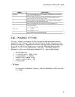
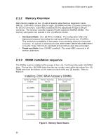
hp workstation i2000 owner's guide 1.3.2 DVD ROM Drive In the i2000 system, the DVD ROM drive in the peripheral bay consists of an IDE device. 1.3.3 Hard Drive Bay The hard drive bay is designed for 3.5-inch-wide hard drives. It can accommodate up to five- (5) 1-inch-high or three- (3) 1.6-inch-high drives. 1.4 Power Supply The chassis is configured with a single, 800 W power supply. It is capable of providing full rated output power over a range of input voltages, 100-240 VAC. The power supply features automatic Power Factor Correction (PFC), and is connected to the system boards using the following connectors: • A 24-pin baseboard connector providing +3.3 Vdc and +5 Vdc • A 22-pin baseboard connector with +3.3 Vdc, +5 Vdc, +12 Vdc and -12 Vdc outputs • An 8-pin connector for memory power with an output voltage 12 Vdc • A 6-pin connector for the processor Power Pod with an output voltage of 12 Vdc • A 16-pin connector with outputs of +5 Vdc and +12 Vdc for peripherals For ease of replacement, the connectors can be disconnected from the power supply and the power supply replaced without removing the system boards or unhooking any connectors from the boards. 1.5 System Cooling Support for eight- (8) fans within four- (4) separate zones (regions of the system) is provided for the following configuration: • Zone 1 - Processor: two- (2) fan headers for two- (2) 120-mm fans. • Zone 2 - Memory: one- (1) fan header for one- (1) 80-mm fan. • Zone 3 - I/O: two- (2) fan headers for one- (1) 92-mm and one- (1) 60-mm fan. • Zone 4 - Exhaust: three- (3) fan headers for three- (3) 80-mm fans, but only one- (1) is populated in the reference system configuration. i2000 utilizes three- (3) wire fans; two- (2) wires provide power, another provides the fan tachometer output. Utilizing a three-wire fan allows the system to monitor the fan speed and control the speed via the power source with sensing from a thermister (on-board or remote). 31
-
 1
1 -
2
-
3
-
4
-
5
-
6
-
7
-
8
-
9
-
10
-
11
-
12
-
13
-
14
-
15
-
16
-
17
-
18
-
19
-
20
-
21
-
22
-
23
-
24
-
25
-
 26
26 -
 27
27 -
 28
28 -
 29
29 -
 30
30 -
 31
31 -
 32
32 -
 33
33 -
 34
34 -
 35
35 -
 36
36 -
37
-
38
-
39
-
40
-
41
-
42
-
43
-
44
-
45
-
46
-
47
-
48
-
49
-
50
-
51
-
52
-
53
-
54
-
55
-
56
-
57
-
58
-
59
-
60
-
61
-
62
-
63
-
64
-
65
-
66
-
67
-
68
-
69
-
70
-
71
-
72
-
73
-
74
-
75
-
76
-
77
-
78
-
79
-
80
-
81
-
82
-
83
-
84
-
85
-
86
-
87
-
88
-
89
-
90
-
91
-
92
-
93
-
94
-
95
-
96
-
97
-
98
-
99
-
100
-
101
-
102
-
103
-
104
-
105
-
106
-
107
-
108
-
109
-
110
-
111
-
112
-
113
-
114
-
115
-
116
-
117
-
118
-
119
-
120
-
121
-
122
-
123
-
124
-
125
-
126
-
127
-
128
-
129
-
130
-
131
-
132
 |
 |
