HP Workstation i2000 hp workstation i2000 owner's guide (a6037-90003) - Page 36
Memory Overview, DIMM installation sequence
 |
View all HP Workstation i2000 manuals
Add to My Manuals
Save this manual to your list of manuals |
Page 36 highlights
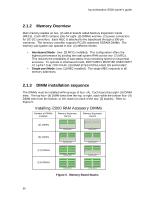
hp workstation i2000 owner's guide 2.1.2 Memory Overview Main memory resides on two- (2) add-in boards called Memory Expansion Cards (MECs). Each MEC contains sites for eight- (8) DIMMs and two- (2) power connectors for DC-DC converters. Each MEC is attached to the baseboard through a 300-pin connector. The memory controller supports PC100 registered SDRAM DIMMs. The memory sub-system can operate in two- (2) different modes. • Interleaved Mode: (two- [2] MECs installed). This configuration offers the highest performance by dividing the total system RAM across two- (2) MECs. This reduces the probability of wait states, thus increasing speed on sequential accesses. To operate in interleaved mode, BOTH MECs MUST BE USED WITH AT LEAST THE TOP FOUR- (4) DIMM SITES POPULATED ON EACH MEC. • Single-port Mode: (one- [1] MEC installed). The single MEC responds to all memory addresses. 2.1.3 DIMM installation sequence The DIMMs must be installed within groups of four- (4). Each board has eight- (8) DIMM sites. The top four- (4) DIMM sites form the top, or right, stack while the bottom four- (4) DIMM sites form the bottom, or left, stack (on each of the two- [2] boards). Refer to Figure 5. Installing i2000 RAM Accessory DIMMs Number of DIMMs Installed Memory Expansion Card A Memory Expansion Card B (4) DIMMs (8) DIMMs (12) DIMMs (16) DIMMs Figure 5. Memory Board Stacks 36
-
 1
1 -
2
-
3
-
4
-
5
-
6
-
7
-
8
-
9
-
10
-
11
-
12
-
13
-
14
-
15
-
16
-
17
-
18
-
19
-
20
-
21
-
22
-
23
-
24
-
25
-
26
-
27
-
28
-
29
-
30
-
 31
31 -
 32
32 -
 33
33 -
 34
34 -
 35
35 -
 36
36 -
 37
37 -
 38
38 -
 39
39 -
 40
40 -
 41
41 -
42
-
43
-
44
-
45
-
46
-
47
-
48
-
49
-
50
-
51
-
52
-
53
-
54
-
55
-
56
-
57
-
58
-
59
-
60
-
61
-
62
-
63
-
64
-
65
-
66
-
67
-
68
-
69
-
70
-
71
-
72
-
73
-
74
-
75
-
76
-
77
-
78
-
79
-
80
-
81
-
82
-
83
-
84
-
85
-
86
-
87
-
88
-
89
-
90
-
91
-
92
-
93
-
94
-
95
-
96
-
97
-
98
-
99
-
100
-
101
-
102
-
103
-
104
-
105
-
106
-
107
-
108
-
109
-
110
-
111
-
112
-
113
-
114
-
115
-
116
-
117
-
118
-
119
-
120
-
121
-
122
-
123
-
124
-
125
-
126
-
127
-
128
-
129
-
130
-
131
-
132
 |
 |
