HP Workstation i2000 hp workstation i2000 owner's guide (a6037-90003) - Page 98
Baseboard Installation
 |
View all HP Workstation i2000 manuals
Add to My Manuals
Save this manual to your list of manuals |
Page 98 highlights
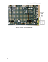
hp workstation i2000 owner's guide Table 24. I/O ADMIN Jumper ADMIN (J8C3) ENABLE 1-2 DISABLE 2-3* * DEFAULT 8.2 Baseboard Installation Once verification of the jumper settings on the baseboard, the I/O board, and the processor board are complete and correctly set, insert the baseboard into the system chassis and center the board utilizing the baseboard alignment pins 1 and 2 (as shown in Figure 49). Use the following steps: 1. Apply a small amount of downward pressure to "press fit" the baseboard onto the alignment pins. The remaining eight- (8) baseboard mounting holes must now be aligned properly. Insert the eight- (8) baseboard mounting screws and secure the baseboard to the chassis. Refer to the locations in Figure 49. 2. Reconnect the three- (3) main power supply connectors at the rear of the baseboard. Refer to Figure 48. 3. Reconnect the forward and rear processor cooling fan connectors J48, J50 and J5, J8, J11 respectively. Refer to Figure 53. 8.2.1 Fan Installation 1. Attach the fan power connectors to the baseboard power connectors J33 and J36. Refer to Figure 53. 2. Reinstall the fan card guide by first aligning it with the screw hole and then snapping it into place (refer to Figure 53). Secure it to the chassis using the mounting screw. 3. Reinstall the two- (2) memory card retention posts and secure them to the baseboard using four- (4) screws (two- [2] each). Be sure to place the retention post, which contains the fan at the front of the baseboard, adjacent to the fan card guide. Refer to Figure 47. 4. Reconnect the retention post fan power cable to connector J46. Refer to Figure 53. 98
-
 1
1 -
2
-
3
-
4
-
5
-
6
-
7
-
8
-
9
-
10
-
11
-
12
-
13
-
14
-
15
-
16
-
17
-
18
-
19
-
20
-
21
-
22
-
23
-
24
-
25
-
26
-
27
-
28
-
29
-
30
-
31
-
32
-
33
-
34
-
35
-
36
-
37
-
38
-
39
-
40
-
41
-
42
-
43
-
44
-
45
-
46
-
47
-
48
-
49
-
50
-
51
-
52
-
53
-
54
-
55
-
56
-
57
-
58
-
59
-
60
-
61
-
62
-
63
-
64
-
65
-
66
-
67
-
68
-
69
-
70
-
71
-
72
-
73
-
74
-
75
-
76
-
77
-
78
-
79
-
80
-
81
-
82
-
83
-
84
-
85
-
86
-
87
-
88
-
89
-
90
-
91
-
92
-
 93
93 -
 94
94 -
 95
95 -
 96
96 -
 97
97 -
 98
98 -
 99
99 -
 100
100 -
 101
101 -
 102
102 -
 103
103 -
104
-
105
-
106
-
107
-
108
-
109
-
110
-
111
-
112
-
113
-
114
-
115
-
116
-
117
-
118
-
119
-
120
-
121
-
122
-
123
-
124
-
125
-
126
-
127
-
128
-
129
-
130
-
131
-
132
 |
 |
