HP Workstation i2000 hp workstation i2000 owner's guide (a6037-90003) - Page 88
Removal of the I/O Board
 |
View all HP Workstation i2000 manuals
Add to My Manuals
Save this manual to your list of manuals |
Page 88 highlights
hp workstation i2000 owner's guide Fan Card Guide I/O Retaining Screws I/O Card Retaining Foot Rear I/O Retaining Screw Memory Card Retention Posts Figure 45. Internal Component Locations 7.5 Removal of the I/O Board 1. Disconnect all I/O card cables and connectors. 2. Remove the two- (2) screws at the top of the I/O bracket located inside the system. 3. Remove the screw holding the I/O bracket to the rear of the system (external). Refer to Figure 46. 4. Remove the screw fastening the plastic retaining foot, at the front of the I/O board, from the baseboard. Refer to Figure 46. 5. Place this card aside on an anti-static surface. 88
-
 1
1 -
2
-
3
-
4
-
5
-
6
-
7
-
8
-
9
-
10
-
11
-
12
-
13
-
14
-
15
-
16
-
17
-
18
-
19
-
20
-
21
-
22
-
23
-
24
-
25
-
26
-
27
-
28
-
29
-
30
-
31
-
32
-
33
-
34
-
35
-
36
-
37
-
38
-
39
-
40
-
41
-
42
-
43
-
44
-
45
-
46
-
47
-
48
-
49
-
50
-
51
-
52
-
53
-
54
-
55
-
56
-
57
-
58
-
59
-
60
-
61
-
62
-
63
-
64
-
65
-
66
-
67
-
68
-
69
-
70
-
71
-
72
-
73
-
74
-
75
-
76
-
77
-
78
-
79
-
80
-
81
-
82
-
 83
83 -
 84
84 -
 85
85 -
 86
86 -
 87
87 -
 88
88 -
 89
89 -
 90
90 -
 91
91 -
 92
92 -
 93
93 -
94
-
95
-
96
-
97
-
98
-
99
-
100
-
101
-
102
-
103
-
104
-
105
-
106
-
107
-
108
-
109
-
110
-
111
-
112
-
113
-
114
-
115
-
116
-
117
-
118
-
119
-
120
-
121
-
122
-
123
-
124
-
125
-
126
-
127
-
128
-
129
-
130
-
131
-
132
 |
 |

hp workstation i2000 owner’s guide
88
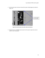
Figure 45. Internal Component Locations
7.5
Removal of the I/O Board
1.
Disconnect all I/O card cables and connectors.
2.
Remove the two- (2) screws at the top of the I/O bracket located inside the
system.
3.
Remove the screw holding the I/O bracket to the rear of the system (external).
Refer to Figure 46.
4.
Remove the screw fastening the plastic retaining foot, at the front of the I/O
board, from the baseboard.
Refer to Figure 46.
5.
Place this card aside on an anti-static surface.
I/O Card
Retaining
Foot
Fan
Card Guide
Memory
Card
Retention
Posts
I/O Retaining
Screws
Rear I/O
Retaining Screw